My guess about impurities in the tube still is the most probable. What if to bake tubes for several hours in 250 degrees oven, then experiment again?
If it is caused by impurities some of them will be absorbed by getter flash, the rest by cathode when they start working. I don't know what kind of molecules getter and cathode absorb, though... I do not know if metal evaporated by hot cathode can be absorbed such a way. But it definitely leaves traces on mica, I know that aging tubes have higher leakage because of this mechanism.
If it is caused by impurities some of them will be absorbed by getter flash, the rest by cathode when they start working. I don't know what kind of molecules getter and cathode absorb, though... I do not know if metal evaporated by hot cathode can be absorbed such a way. But it definitely leaves traces on mica, I know that aging tubes have higher leakage because of this mechanism.
I've never grounded pin 9 on 6N1 or 6N2 and never had any problems.
Thanks for your feedback Ian - I guess you made the same assumption as me that it shouldn't matter if it is grounded or not. I am coming to the conclusion that I may have had a batch of these valves that are prone to this problem.
EDIT: I just saw your update Ian - yes 6N2P-EV valves do not demonstrate this phenomenon - it has only been the 6N2P valves that have this effect
EDIT: You can ignore the "images" in the original post - they are smilies from another forum post
Last edited:
To investigate what is happening, connect a DVM from pin9 to ground and see what happens to the voltage on the screen when it is left floating (apart from the DVM input impedance 10M?). If it is collecting electrons (from anode holes?) then it will go negative. On the other hand, it could go positive if each electron arriving kicks out more than one secondary electron - it could get very positive!
If it can receive electrons from the triode structure then it can affect the triode structure. Does the valve have anode holes facing the screen? This could be the difference between those which show the effect and those which don't. Or it could be the exact metal or coating of the screen affecting secondary electron emission.
An update - I have just done some testing with the pin 9 shield disconnected and measuring for any voltage on this pin. The results are inconclusive as a) it is very high impedance and my multimeter has an input impedance of 12Mohm and b) the readings were variable. I read a fluctuating negative voltage of about -300mv DC. I attempted to get an ac reading, but the reading of approx 1v ac maybe due to stray capacitances. I must admit, I was hoping for a high DC voltage which would support Wavebourne's theory of leakage from the plates across the mica supports but no

DF96: "If it can receive electrons from the triode structure then it can affect the triode structure. Does the valve have anode holes facing the screen? This could be the difference between those which show the effect and those which don't. Or it could be the exact metal or coating of the screen affecting secondary electron emission."
I think you may be on to something - I have compared the 6N2P with the 6N2P-EV - the 6N2P has a round hole in the plate facing the shield whereas the EV version does not have a hole - could this be it? That the shield collects electrons and acts as an extra electrode in the triode??
I think you may be on to something - I have compared the 6N2P with the 6N2P-EV - the 6N2P has a round hole in the plate facing the shield whereas the EV version does not have a hole - could this be it? That the shield collects electrons and acts as an extra electrode in the triode??
I must admit, I was hoping for a high DC voltage which would support Wavebourne's theory of leakage from the plates across the mica supports but no
Wavebourne's theory is, if the shield does exist between anodes, it helps. I never ever experienced similar problems like you describe, most probably because I ground a shield between anodes when it exists, and I don't hesitate to use grid stoppers.
Edit: I wonder, if 12AX7 that used in almost all guitar amps would work well in your amp without grid stoppers, like on your schematic...
Last edited:
I think you may be on to something - I have compared the 6N2P with the 6N2P-EV - the 6N2P has a round hole in the plate facing the shield whereas the EV version does not have a hole - could this be it? That the shield collects electrons and acts as an extra electrode in the triode??
There you have it. It is very well possible that the shield potential (which you might not be able to measure with a ~10Megohm DMM) changes the tube curves.
In an ironic twist, the best samples (those having the least leakage between the shield and other electrodes) would probably suffer most from this effect
I have compared the 6N2P with the 6N2P-EV - the 6N2P has a round hole in the plate facing the shield whereas the EV version does not have a hole - could this be it? That the shield collects electrons and acts as an extra electrode in the triode??
Could you post some photos if possible?
Why does it not come back after disconnecting the shield from earth?
Regards
M. Gregg
It may come back but only slowly as the screen charges up again. You must have very high quality valveholders, as any surface moisture would make the charge leak away. Are you in a hot dry region?
I am pleased that my prediction of anode holes seems to be correct. After suggesting measuring it with a DVM I realised that the impedance would be so high that even a DVM would just discharge it. Try running it for a while with no pin9 connection and see if the problem comes back. Also try putting some AC on pin9 (plus DC bias?) and see what effect it has on the triode.
My guess is that if the screen is much below the anode potential it will have little effect. If it is near or above the anode potential then it will attract electrons, and modify the triode behaviour. You could try just charging the screen up to anode potential then isolating it; this would happen naturally but slowly via the mica. My guess is that for higher screen potentials secondary emission would push it even higher. This may be why you get a binary response: low screen potential collects just a few low energy electrons so goes more negative and has even less effect, while high screen potential gets lots of fast electrons and loses even more through secondaries so goes more positive and has greater effect.
It may come back but only slowly as the screen charges up again. You must have very high quality valveholders, as any surface moisture would make the charge leak away. Are you in a hot dry region?
I am pleased that my prediction of anode holes seems to be correct. After suggesting measuring it with a DVM I realised that the impedance would be so high that even a DVM would just discharge it. Try running it for a while with no pin9 connection and see if the problem comes back. Also try putting some AC on pin9 (plus DC bias?) and see what effect it has on the triode.
My guess is that if the screen is much below the anode potential it will have little effect. If it is near or above the anode potential then it will attract electrons, and modify the triode behaviour. You could try just charging the screen up to anode potential then isolating it; this would happen naturally but slowly via the mica. My guess is that for higher screen potentials secondary emission would push it even higher. This may be why you get a binary response: low screen potential collects just a few low energy electrons so goes more negative and has even less effect, while high screen potential gets lots of fast electrons and loses even more through secondaries so goes more positive and has greater effect.
Yes, the valveholders are high quality ceramic and humidity is fairly low here at this time of year. I have yet to test it, but I think you are correct - that if left for some time, the distortion will return due to electrons collecting on the shield. Thanks for your insight!

I am looking at a 6N2P now, and something else I see is that the shield is also attached to the getter, and it hangs right over the grid support rods of one of the triodes where they poke through the mica. This might not be the case for all samples though (I only have one).
As others have suggested, I have done further tests with applying several hundred volts positive to the shield. This immediately induces the distortion effect and the distortion remains until the shield is grounded again. So it seems that there are two mechanisms happening - firstly some leakage as has been suggested between the plates and the shield which builds up a positive charge on the shield. Secondly, because there is a hole in the plate this voltage on the shield has a deleterious effect on electron flow causing this distortion.
So evidently in the valves that I regarded as "faulty", there was an unhappy congruence between these two issues causing the distortion. Either no leakage - or no hole in the plate, and this phenomenon would not occur.
Of course this is all now academic as all shields will be grounded in future, nonetheless, I have been very keen to understand why this originally happened.
Last edited:
So it seems that there are two mechanisms happening - firstly some leakage as has been suggested between the plates and the shield which builds up a positive charge on the shield. Secondly, because there is a hole in the plate this voltage on the shield has a deleterious effect on electron flow causing this distortion.
I suppose there is no chance that a few electrons miss the anode and go straight through the hole, building the shield a negative charge?
That would be interesting to know. I expect that a zero voltage screen might stay there, or slowly rise due to mica leakage. A middle voltage screen would go lower as it collects electrons through the hole, so the two effects might cancel. A high voltage screen would go higher due to secondary emission. I am not sure where the boundary is between these regions.
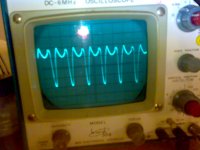
Have retested the 6N2P with a range of voltages on the shield - as mentioned before, when the shield is taken to +250V DC, the distortion is evident. Ground the shield and distortion gone. I have just done further tests with -300V applied to the shield (via limiting resistor) and no distortion. I then decided to check for any AC component on the floating shield. Turns out that there is a large AC component (probably larger but for the input impedance of my CRO) on the shield. This AC component is a distorted version of the input sine wave (see attached photo) and is probably in the hundreds of volts peak to peak. No wonder this had such an adverse effect on the triode operation - when the triode was driven a distorted version of the signal develops on the shield. This then distorts the normal operation of the triode. So it appears that the distortion issue was related in part to DC conditions on the shield, but also the presence of a large distorted AC signal on the shield is the primary reason for the distortion.
So it seems that my initial theory (electrons building up a negative charge on the plate) was not the mechanism for the distortion. Rather it seems that minute leakage in the valve across the mica support or capacitance between the plates and the shield builds up a POSITIVE voltage on the shield. This positive potential (with a large distorted AC signal superimposed) then has an adverse effect on electron flow in the valve due to the hole in the plate facing the shield.
So it seems that my initial theory (electrons building up a negative charge on the plate) was not the mechanism for the distortion. Rather it seems that minute leakage in the valve across the mica support or capacitance between the plates and the shield builds up a POSITIVE voltage on the shield. This positive potential (with a large distorted AC signal superimposed) then has an adverse effect on electron flow in the valve due to the hole in the plate facing the shield.
Attachments
Last edited:
- Status
- This old topic is closed. If you want to reopen this topic, contact a moderator using the "Report Post" button.
- Home
- Amplifiers
- Tubes / Valves
- 6N2P - WHAT THE?????????????