G2 is driven by the HV Mosfet follower directly, with a resistor/divider drive to grid 1. Bottom of the R divider is to the cathode.
There is some discussion of how it works in the referenced thread before the amplifier schematic. Briefly, it is just positive g2 drive, with a low current (positive) drive to grid 1. The grid 1 drive voltage slowly saturates (from grid 1 current interception) with increasing grid2 + drive, compensating for the 3/2 power law from grid 2 drive alone. The resistor from grid 2 to grid 1 has to be chosen (per tube type) to get the right compensation for linear overall drive.
As I recall, testing Crazy/Twin with a 26LW6 tube found some linearity improvement by off-setting the bottom of the resistive divider by a few volts from the cathode. Likely some thermal junction potential from dissimilar hot metals in the tube connection spot welds that needed nulling out. Could be different for different tubes.
Last edited:
I did not say the 6LW6 was safe in triode mode when operated with plate/screen voltages that exceed the maximum rating of the screen: 280V and 7Watts (25mA). I would recommend a little lower voltage and current just to be sure, say 250V and 20mA. I am sure it will not have much power there, but it should work.
And in triode mode with those parameters, the plate might not be drawing much current and the u might be low. But the worst of all that would be the power hungry filament, 6.3V @ 2.65A. Too much filament power wasted, versus the low power out in triode mode SE. There are much better Pentodes and Beam Power tubes for triode wired SE.
Of course, there would have to be a small screen resistor to the plate, so you could monitor the screen current.
Who knows, maybe the screen might die when the parallel screen/plate combination swings upward as the tube current reduces, say from 250V to 350V (would it arc over?).
Last edited:
(pulling grid 1 positive).
I used a mosfet with a 20K grid to -150 volts resistor. I doubt the grid voltage changed enough to cause runaway. The tubes all appeared to die from contamination of some sort as evidenced by the blue or purple glow. How, or where, I do not know. The blue lightning in a bottle tube is still around, just waiting for me to crank up the big power supply and blow it to pieces. It is now so gassy that I don't even need to power the heater, just add B+ and it lights up! I have a gassy 6AS7 too. I have a special surprise waiting for that one, but I will need two big power supplies for that.
Sometime after next weeks big hamfest. I have been on the phone making tube deals for 3 days......about 1500 tubes will change hands at the show and before. 800 arrived by mail today. I need to test a bunch of tubes tomorrow. Time to build a few new projects.
My hope and goal was to operate Class A at a B+ above the mentioned tetrode kinks. I can go with a variety of B+ and screen voltages since it’s a scratch build where I just want to see how the 6LW6/26LW6 will sound run in standard Pentode mode with a little feedback. That’s where I got my operating points. The max screen voltage is a touch higher on this than most, so I thought 200-225V would work, and around 400V B+, but I could go higher or lower. The outputs are Edcor 15W, so that’s another limiting factor. I know I can probably push the tube past that power and current rating, but not with this set of output iron.
I’ve done a bunch of 6CB5 amps in triode and want to try something new.
I’ve done a bunch of 6CB5 amps in triode and want to try something new.
Has anyone tried the 6LW6 or 6LF6 in SE using a regulated screen supply? Has a max screen voltage of 275V, so UL isn’t a great option. I read somewhere on this forum that the 6LW6 isn’t very linear run in Pentode, but I haven’t seen anything else on it.
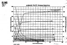
The only way I'd consider a 6LW6 for SE would be a Class C RF power amp. These horizontal deflection PAs don't give any examples in the spec sheets for audio because the most linear part of the plate characteristic is well within red plate territory. (See attached plate characteristic).
For audio, you'd need: VPKQ= 200V; IPKQ= 1.0A for a PD= 200W. It might sound quite good, but not for very long. For SE, you'd have to drop that V2K way down, and lose a lot of power capability -- so much that you might as well fuggaboudit and use a pentode designed for audio for the SE output, like a 6AQ5 (or some other 6V6-oid).
6LW6s (and other TV HD finals) work best as PP, Class AB1 stages. I don't have any 6LW6s, but a half dozen of the 36LW6 variety and one 26LW6.
I have a 2.5K SE output, so I think I’d like to try it with 80-90mA bias and 400V B+ with 200-250V on the screens.
Thanks for any information!
That'll put you way down into the bottom of the plate characteristic with such a shallow loadline you'll put the screen at risk of overdrive failure. Being so far towards plate current cutoff won't sound very good either.
Attachments
I am working on a "way out of this darkness." It is beginning to show some hope beyond the pile of blown parts, and dead tubes. This journey has even taught me that I can cause a vacuum tube to shatter violently due to what turned out to be a really DUMM arithmetic error. Not ready for prime time, or even to be revealed yet but I am betting Tubelab's future on it.
just received a huge box of test subjects (tubes) and I will pick up another at the Dayton hamfest later this week. I have spent the past two days testing some tubes to trade for my next batch of test subjects on Thursday. Tubelab is out of money, but I have a box full of Telefunken and Mullard tubes to trade.
What's up? Well I have been working on something I called my Grand Unified Theory of vacuum tube circuitry off and on for several years. I have a pile of old test boards to show for it.
I have come up with a circuit wrapped around a vacuum tube containing some silicon and vacuum devices and a few other parts. I call it the Composite Electron Device because we tend to name things.
Why do we need this? Here is a hand drawn curve of one of the devices that survived my torture. The raw data was taken with old school linear power supplies so the lines are a bit off, especially the green and purple pair, but this is a SWEEP TUBE and these are triode curves to 550 volts. I stopped there because that's as far as the old Fluke 407D will go! I have swueezed 80+ watts from a small pair of these in push pull. No testing in SE yet.
I will start a new thread when I have this stuff fully tamed.
Attachments
Do you have any 6AV5GA?
They will work fine as a triode up to about 300 volts. There were some 6B4GA tubes made by Sylvania that actually contained 6AV5GA guts connected up as a triode.
My hope and goal was to operate Class A at a B+ above the mentioned tetrode kinks....
The tetrode kink is *proportional* to Vg2.
With these very juicy tubes, you can set Vg2 very low (even 40V), get ample peak current, without trespassing into kink-turf.
I just got my internet back after two days of outage...grumble, grumble
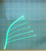
G2 drive or Crazy/Twin Drive can get those 6/26/36LW6 tubes to run linearly at reasonable current.
Crazy/Twin drive takes about 2/3 the peak grid 2 voltage of G2 only drive for the same current peaks. So is safer for the tube. But a little more complex to set up. (2 extra resistors)
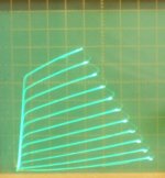
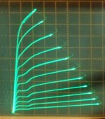
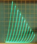
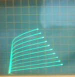
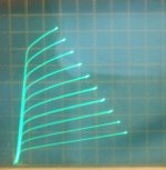
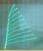
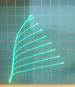
Below is: (50 mA/div Vert., 50V/div Horiz. for all)
1) 36LW6 in Crazy/Twin drive +5V steps
2) 36LW6 in G2 drive +5V steps
3) 36LW6 in normal grid 1 drive (probably -1V steps, not recorded)
4) 36LW6 in triode (Mu 3.7, probably around -9V steps, not recorded)
Crazy, G2 or normal pentode will still require some kind of N Fdbk to lower the output Z.
G2 drive or Crazy/Twin Drive can get those 6/26/36LW6 tubes to run linearly at reasonable current.
Crazy/Twin drive takes about 2/3 the peak grid 2 voltage of G2 only drive for the same current peaks. So is safer for the tube. But a little more complex to set up. (2 extra resistors)
Below is: (50 mA/div Vert., 50V/div Horiz. for all)
1) 36LW6 in Crazy/Twin drive +5V steps
2) 36LW6 in G2 drive +5V steps
3) 36LW6 in normal grid 1 drive (probably -1V steps, not recorded)
4) 36LW6 in triode (Mu 3.7, probably around -9V steps, not recorded)
Crazy, G2 or normal pentode will still require some kind of N Fdbk to lower the output Z.
Attachments
Last edited:
Is crazy drive worth it in push pull vs. standard Pentode? I’m still doing a push pull 26LW6 amp into 1.5K.
For class AB in P-P, the standard grid 1 pentode mode can probably be brought close to Crazy Drive linearity by adjusting the amount of class A overlap.
Crazy Drive also needs to be carefully analyzed for crossover distortion yet, although Mickeystan seems to have gotten comparable results to standard pentode. Crazy drive reverts to mostly grid 1 drive near cut-off, so not too surprising they are similar. There could be an efficiency gain, with Crazy Drive not requiring as much conduction overlap in the class A P-P portion. Needs to be measured. Grid 2 drive certainly gets better efficiency, and Crazy Drive is just a souped up grid 2 drive.
One clear disadvantage of either G2 drive or Crazy Drive is the need for a HV driver stage that can handle grid current (g2 mainly). And normal grid 1 drive will leave one with more output stage gain for any N Fdbk loop. But the HV driver needed for grid 2 or Crazy Drive already puts more gain in the loop too. So it's a trade-off of a harder driver stage design (and likely Mosfet follower) versus simplicity for likely somewhat better linearity and efficiency.
A class A SE stage is where G2 or Crazy Drive would really shine for linearity. But both need some kind of N Fdbk to lower the output impedance.
Last edited:
I’m still doing a push pull 26LW6 amp into 1.5K.
1.5K is a bit low for a single pair of tubes. Pure pentode would require a good bit of feedback to get the output impedance down and I would keep the output power under 175 watts. Screen or dual / crazy drive would likely require a bit more feedback, but may give a bit more power or efficiency.
I plan to build a kilowatt (500 WPC) audio amp using 36LW6's or 35LR6's once I work out the details. It will use conventional G1 drive, or Composite Electron Device mode if it proves worthy in lower power testing. I have a pair of 1250 ohm OPT's and I will use 4 or 6 tubes per channel. B+ will be in the 650 to 700 Volt range.
Any type of screen driven design can self destruct with continuous operation at full power for say a minute. Dual / Crazy drive can help with this, but tubes don't like having their grids driven highly positive while the plate is near zero for more than a few milliseconds. This should not be a problem with normal music use, but I want my amp to eat my guitar playing when highly overdriven, even if it will never see such use.
I have seen 4 X 35LR6 deliver 525 watts on 650 volts of sine wave at 5% THD through my OPT's with Pete Millett's big red board for over 30 seconds. That board uses conventional G1 drive without mosfets, so no positive G1 use, and G2 is fixed at 150 volts.
As George mentioned, over-driving a G2 or Crazy/Twin Drive setup will imperil the grid 2 (and grid 1 too for Crazy/Twin).
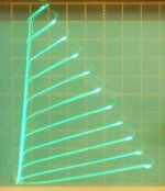
Below are some pics of the Rg2g1 selection process for Crazy/Twin drive, with the resistor Rg2g1 from grid 2 to grid 1 being varied. (the 6HJ5 tube used here)
(all are 50 mA/div Vert., 50V/div Horiz.)
1) Rg2g1 = 350 Ohm
2) Rg2g1 = 600
3) Rg2g1 = 700
4) Rg2g1 = 1780
5) Rg2g1 = 2750
All of the curve sets eventually end up with the rolled over left side diode line topside if you drive them to high enough current. (Which means the grids are absorbing the cathode current! Although Rg2g1 is protecting grid 1 to a fair extent by limiting the drive V and current to grid 1) So one has to use a higher value Rg2g1 for higher current operation. (these graphs go up to 1/2 Ampere current) Eventually (with higher Rg2g1) the linearizing effect is diminished (and the gain decreased, g1 not doing much). So using an unusually lowish Zprimary OT (really high tube current) for the tube is not recommended for Crazy/Twin Drive, or for G2 drive.
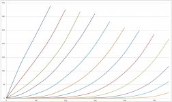
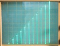
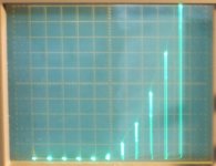
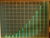
However, for a well optimized Crazy/Twin design the linearity gains can be impressive. Below are some drive voltage to plate current graphs for various drive modes. A straight (sloping) line would be linear.
(26LX6 tube used here, 50 mA/div Vert. )
6) normal g1 drive pentode
7) Crazy/Twin drive
8) the low current end (magnified, 10 mA/div) of Crazy/Twin drive for an overlap/crossover study with another P-P tube.
Below are some pics of the Rg2g1 selection process for Crazy/Twin drive, with the resistor Rg2g1 from grid 2 to grid 1 being varied. (the 6HJ5 tube used here)
(all are 50 mA/div Vert., 50V/div Horiz.)
1) Rg2g1 = 350 Ohm
2) Rg2g1 = 600
3) Rg2g1 = 700
4) Rg2g1 = 1780
5) Rg2g1 = 2750
All of the curve sets eventually end up with the rolled over left side diode line topside if you drive them to high enough current. (Which means the grids are absorbing the cathode current! Although Rg2g1 is protecting grid 1 to a fair extent by limiting the drive V and current to grid 1) So one has to use a higher value Rg2g1 for higher current operation. (these graphs go up to 1/2 Ampere current) Eventually (with higher Rg2g1) the linearizing effect is diminished (and the gain decreased, g1 not doing much). So using an unusually lowish Zprimary OT (really high tube current) for the tube is not recommended for Crazy/Twin Drive, or for G2 drive.
However, for a well optimized Crazy/Twin design the linearity gains can be impressive. Below are some drive voltage to plate current graphs for various drive modes. A straight (sloping) line would be linear.
(26LX6 tube used here, 50 mA/div Vert. )
6) normal g1 drive pentode
7) Crazy/Twin drive
8) the low current end (magnified, 10 mA/div) of Crazy/Twin drive for an overlap/crossover study with another P-P tube.
Attachments
-
 rsz_26lx6_twin_54v_54vs_50_50.jpg79.1 KB · Views: 26
 -
 rsz_26lx6_26vhtr_g1pentode.jpg82.6 KB · Views: 19
 -
 rsz_6hj5_cr_2750_50_50.jpg63.1 KB · Views: 21
 -
 rsz_6hj5_cr_1780_50_50.jpg67.3 KB · Views: 19
 -
 rsz_6hj5_cr_700_50_50.jpg65.2 KB · Views: 26
 -
 rsz_6hj5_cr_600_50_50.jpg57.5 KB · Views: 27
 -
 rsz_6hj5_cr_350_50_50.jpg56.9 KB · Views: 156
 -
 rsz_26lx6_g2_g1_10ma_2vsteps_0center (1).JPG293.7 KB · Views: 21
Last edited:
I wanted to use four in PPP into 1.5K for around 200W, but I’ve been suggested to use a single pair into 1.5K by several people.
I tried 2 tubes into 1250 ohms VS and they really didn't like it. Efficiency went down, distortion and output impedance went up. I also tried 1650, 2500, 3300 and 5000 ohms on 36LW6's and 35LR6's. The efficiency peaked at 2500 ohms per pair, then dropped off, although the 36LW6's hung in there longer than the 35LR6's, as they have more plate area and a bigger cathode.
4 6LW6's in PPP into 1250 ohms will do over 500 watts from 650 volts. The same tube combination into 1.5K will do 450+ watts, or anything less just by reducing the plate voltage.
200 watts with 4 tubes should be doable on somewhere around 450 volts, the tubes will be happy since they aren't straining to drive 1500 ohms per pair.
The output impedance will be lower with 4 tubes, so less feedback will be needed. No tricks are needed, just drive G1 and connect the screens to a stiff power supply in the 150 to 200 volt range through a 100 ohm 2 watt resistor per tube.
I would use a simple mosfet follower for the screen "regulator" and make it adjustable from 150 to 200 volts. Tune it against the bias voltage for the best trade off of efficiency VS distortion.
You could probably make a pair work at 200 watts, but they wouldn't be happy. If you have the space, and the tubes, then use them.
I may have more testing done before you build your amp but it is a month or so away before I start it. I did see a pair of 36LW6's crank out 170 watts before a stupid mistake caused the board to arc over ending the fun.
I am prepping for the Dayton Hamfest today and tomorrow, then I'll be gone for a few days. I will return with a BIG box full of test subjects (tubes), and whatever else I find......I got the 35LR6's there in 2010, I think I got 45 of them for $100.
- Status
- This old topic is closed. If you want to reopen this topic, contact a moderator using the "Report Post" button.
- Home
- Amplifiers
- Tubes / Valves
- 6LW6 in SE?