Chris,
I am running a 7591 amp (triode mode) using 2 vintage Partridge 300-0-300 @ 135mA power transformers in dual mono configuration. The output tubes are drawing about 45 mA each with B+ of 390V (SS rectification), 12AT7 LTP's drawing 6 mA per pair. The power transformers get quite hot after an hour or so. I would go with the 250mA rated transformer.
Steve
As for heat sinking, the chassis is solid aluminium plate, perhaps using the chassis as a sink would be OK?
Maybe, maybe not. I would mount the pass device somewhere where you could slap a heatsink just in case.
Any further input as to the power transformers?
I like the 300BX personally.
As for the regulator, I share it with a caveat. I have not tested it with lab equipment yet. (just got parts to build a dummy load) I have done listening tests and it sounds a lot better than the unregulated supply, more powerful.
Hopefully some folks will stop by and review my design. I'd hate to pass on something that doesn't work perfectly
") .
.Attachments
I was looking at the data sheet and seeing about 80mA draw. I had assumed that it was per tube, but looking again I see that it is per pair. As I am building monoblocks, I guess that even 200mA is going to be overkill. Since the 300BX is 250mA and cheaper, I am thinking of going with that. Also opens opportunities for future builds with recycled parts. The idea of a regulated supply is growing on me, not least because of the saving in space, weight and cost of a choke input or semi choke input design. I have a pair of Chinese "250mA 10H" chokes, but don't trust them for choke input.
Don't sweat the design. I am going to be going slow with this project so there is going to be plenty of opportunity for design review. My eagerness in the last few days is due to me going to LA with work next week and saving some (a lot?) money on shipping the transformers. I suspect that I will not have an opportunity to travel to LA again for quite some time, so want to take advantage of the trip.
Cheers,
Chris
Chris,
A few points, in no particular order.
The 21 lb. "gorilla" is for a stereoblock. The smaller Hammond model 193M is fine in monoblocks. The Chinese chokes already in your possession would be fine as the 2nd inductor in the ARRL recommended LCLC filter arrangement.
If you regulate B+, you MUST regulate the bias supply.
None of the Hammond power trafos with "universal" primaries are suitable for use with choke I/P filtration, either pure or pseudo. OTOH, not much of a "fudge factor" capacitance will be needed to bring the rail voltage into line, if an AnTek AN-4T450 is employed as the power trafo, along with choke I/P filtration. Use 1 of the 6.3 VAC windings for the 6AU4 heaters and the 2nd for all other tubes.
An "El Cheapo" is a 2 stage PP amp using a 12AT7 LTP splitter/driver. Usually, "12" W. tubes are employed. The 7591 is as easy to drive as "12" W. types. Look at the 7591 data sheet, again. Notice that roughly -25 V., on g1, is sufficient to cut it off. The max. O/P of a CDP is 2 VRMS, which is 2.83 V. peak. Assuming a conservative 15X stage gain, for the LTP, you get over 42 V. at the 7591 control grids. That's more than enough to drive the NFB loop and push the "finals" into clipping. Fisher and Scott got great "milage" out of using the same small signal circuitry for both "12" W. tubes and 7591s. I propose you walk the trail they blazed.
When you get to the US, PM me over on AudiophileTalk, with you hotel room's phone number. I'll call you, as my charges are fixed.
A few points, in no particular order.
The 21 lb. "gorilla" is for a stereoblock. The smaller Hammond model 193M is fine in monoblocks. The Chinese chokes already in your possession would be fine as the 2nd inductor in the ARRL recommended LCLC filter arrangement.
If you regulate B+, you MUST regulate the bias supply.
None of the Hammond power trafos with "universal" primaries are suitable for use with choke I/P filtration, either pure or pseudo. OTOH, not much of a "fudge factor" capacitance will be needed to bring the rail voltage into line, if an AnTek AN-4T450 is employed as the power trafo, along with choke I/P filtration. Use 1 of the 6.3 VAC windings for the 6AU4 heaters and the 2nd for all other tubes.
An "El Cheapo" is a 2 stage PP amp using a 12AT7 LTP splitter/driver. Usually, "12" W. tubes are employed. The 7591 is as easy to drive as "12" W. types.
Look at the 7591 data sheet, again. Notice that roughly -25 V., on g1, is sufficient to cut it off. The max. O/P of a CDP is 2 VRMS, which is 2.83 V. peak. Assuming a conservative 15X stage gain, for the LTP, you get over 42 V. at the 7591 control grids. That's more than enough to drive the NFB loop and push the "finals" into clipping. Fisher and Scott got great "milage" out of using the same small signal circuitry for both "12" W. tubes and 7591s. I propose you walk the trail they blazed.When you get to the US, PM me over on AudiophileTalk, with you hotel room's phone number. I'll call you, as my charges are fixed.
I was looking at the data sheet and seeing about 80mA draw. I had assumed that it was per tube, but looking again I see that it is per pair.
This is the idle current per pair. Full power current will be in the 150+ mA range under normal operating conditions. Current at clip can be somewhat higher. I have measured peak currents on a P-P pair of Chinese 6L6GC's at over 400 mA when the OPT saturates. In normal HiFi use these peak currents are rarely if ever seen, and since the average power is usually 10 to 20 db below the peak level, the average current can be safely assumed to be close to the idle current.
The extreme current measured above was in a guitar amp application. I built quite a few guitar amps several years ago that used P-P 6L6GC's. Since I was building them on a budget, I used my old friend the Allied 6K7VG transformer. This is really a Hammond 274BX which is a close relative of the 374BX you used in the Simple SE. After 10 years of operation ALL of those guitar amps are still going with no transformer failures.
I have used the 6K7VG in HiFi amps as well. One of these transformers will power a single channel of 6L6, EL34, or KT88 up to 50 watts without breaking a sweat. I used one to power a two channel amp of about 30 WPC. That ran hot and this is not recommended especially since the owner removed the 6L6GC's and installed KT88's which draw far more current.
Your original proposal was for two monoblocks of 20 to 30 watts each. The original idea called for a power supply in the 375 to 450 volt range depending on the final choice of operating mode and circuit. This voltage requires a power transformer in the 325-0-325 to 360-0-360 volt range which as we all have found is hard to get. Voltage regulation was proposed which makes the circuit design more complex, but generally results in a better sounding amplifier. Since the circuitry will be chosen and designed at a later date, but the transformer choice needs to be made now, voltage regulation may make sense. This also allows greater flexibility in choosing the transformer.
I think that your two choices (300BX or 378X) will work, but the raw B+ voltage will be over 500 volts resulting in excessive dissipation in the regulator pass element, especially if you wind up needing a 370 volt B+ for your amp. Maybe the 374BX would be sufficient. They produce more than enough voltage for any of your possibilities, and we all know that they can power 2 X 6L6GC even in class A (Simple SE) without straining. They would save a few bucks. In either choice 10 to 20 watts will be dissipated in the regulator. I have found that the chassis may not support this level without additional help, depending on the thickness of the metal.
I have used a regulator circuit very similar to the one shown by Spread Spectrum. It is a derivative of the Maida design shown in an old application note available on the National Semiconductor web site. My version uses a big ST Micro mosfet, and the other component values were tweaked for minimum ripple (both audio and 120Hz) at full load. I use it for testing and it is NOT short circuit proof as some claim, but this is not a requirement in an amplifier.
I hesitate to bring up another possibility this late in the game, but... Since you already have 2 chassis, it is possible to put a 2 channel power amp on one chassis, and a regulated supply on the other. This does mean an umbilical cord between the chassis. It does also mean that you can use one larger power transformer for both channels and independent voltage regulators for each channel. One big transformer is usually cheaper than two smaller ones. For this application you can use the Hammond 378CX or the One Electron BFT-1B.
If you regulate B+, you MUST regulate the bias supply.
I use the simple source follower regulator that I posted earlier for the bias supply.
Thanks for the replies!
Would you know, as I had to place an order, I have already ordered two of the Hammond 400-0-400 250mA 300BX transformers. I placed the order last night (Sydney time) with a caveat that if they could not ship them in time to arrive by 15th, not to bother. I am just about to step out the door on a quick trip to Perth, back Monday morning, so thought that to wait till then to order would be cutting it too fine. Have not had a response from AES yet, but if they cannot fill the order I think I will probably have Edcor build some customs to the exact spec required, as I am in no rush. Eli, I will take you up on your offer! George, thanks for your ongoing help!
Thanks again Gentlemen.
Chris
Thanks guys so far,
I am home for a day between trips, of to LA via Auckland tomorrow. For better or worse, I am now committed to the Hammond 400-0-400 transformers. I am interested in why the Hammonds are not suitable for a choke input. I am sure there is a good reason, but my searching has come up dry.
Regulated power supply looks interesting, as I have not done one before (for a valve amp). Looking at Mosfet Follies it looks like I can use something like this as a B+ reducer. Looking at that page also sparks the interest to ask the question: would a mosfet source follower for the power valves improve the design?
Thanks again,
Chris
I don't know if I would use the Mosfet B+ reducer. If you are going to dissipate some power to knock down the voltage, you might as well attenuate the ripple at the same time (regulator). A heatsink is your friend.
Source followers would have some added benefits, but would add some complexity (a negative supply). You would also have to set up a fixed bias scheme and adjust bias on the power tubes individually. You would be immune to blocking distortion. You may want to try building without and leave some space to experiment later. It just depends on how ambitious you are.
Source followers would have some added benefits, but would add some complexity (a negative supply). You would also have to set up a fixed bias scheme and adjust bias on the power tubes individually. You would be immune to blocking distortion. You may want to try building without and leave some space to experiment later. It just depends on how ambitious you are.
Thanks again.
Complexity is not necessarily a bad thing. I already have a couple of amps, and I am looking at this project as my sanity break from study and to divert my attentions from a not so successful relationship . I am thinking that something that takes a few months to construct will be a good thing. Hopefully I will learn something along the way too.
The continuing guidance and patience shown by the mentors above has been great!
Chris
Complexity is not necessarily a bad thing. I already have a couple of amps, and I am looking at this project as my sanity break from study and to divert my attentions from a not so successful relationship
. I am thinking that something that takes a few months to construct will be a good thing. Hopefully I will learn something along the way too.The continuing guidance and patience shown by the mentors above has been great!
Chris
Complexity is not necessarily a bad thing.
Then I'd do the source followers. Bias stability will not be an issue and you will be able to present a very easy load to the driver stage for low distortion. Good things.
Maybe your bias tap would give you enough voltage for a negative rail, maybe you will need a separate transformer.
Thank you again,
I don't think that I am the sharpest tack in the box when it comes to these things, so the continuing patience and assistance is welcome. Has someone done a similar thing with these or similar valves that can share a few words re design or give a few pointers? I was looking at Tubelab's Power Drive Cookbook and was thinking maybe of combining the power drive mosfet setup with the "El Cheapo" 12AT7 splitter with CCS driver? Is this a good starting point?
Oh, BTW, if Eli is reading, when I get to LA I will have internet access in room, so will be able to chat on Skype if that is of any assistance...
Thanks again,
Chris
Has someone done a similar thing with these or similar valves that can share a few words re design or give a few pointers? I was looking at Tubelab's Power Drive Cookbook and was thinking maybe of combining the power drive mosfet setup with the "El Cheapo" 12AT7 splitter with CCS driver? Is this a good starting point?
I am not familiar with the "El Cheapo" so I don't know how the 12AT7 is configured. I have used them in concertina and LTP configurations with good results. My preference is toward the LTP if the complications of negative voltage supplies and CCS's aren't an issue, but the Simple P-P uses a 12AT7 in concertina configuration.
I have been working on a "universal P-P driver" as time permits over the past year. Right now there are three different versions of the design being tested that use 9 pin tubes. I have an additional version breadboarded that uses octal tubes (6SL7/6SN7). All have similar topology. The differences lie in the placement of the CCS's and coupling caps. I discovered the topology about 10 years ago when I did my 300Beast P-P amp. That amp is the only amp that I have kept for that long and it just sounds right.
The first stage is a LTP using a 12A*7 or 6DJ8. A 5751 was used in the 300Beast. Tube choice depends on circuit requirements. The second stage is a differential amp using tubes (6FQ7 or others) feeding mosfet followers (PowerDrive) to provide drive current if needed. I hadn't discovered the PowerDrive yet when I did the Beast so it used a differential SRPP using 6FQ7's.
I am trying to come up with one driver design that can be used for everything from a pair of 6L6GC's to screen driven sweep tubes, cathode follower output stages and monster transmitting tubes. The 6L6GC are really easy to drive compared to all of the other choices and any 4 of my prototypes are more than capable of driving them.
Instead of tinkering with 4 seperate breadboard designs, I decided to commit the prototype design to a PC board. The board has far more circuitry than needed, but it allows me to explore all of the possibilities by selectively populating the PC board. I started the layout in mid December, but life keeps getting in the way. It should be done in the next week or two. Then some experiments will be performed to determine the most optimum topology. I will post the latest schematic as it evolves.
I got 8 big fat sweep tubes for cheap off of Ebay and I have a new 600 volt 1.5 AMP power supply that I am itching to try out. It has been too long since anything glowed here. I should have something figured out before you are ready to build.
chrish said:I am interested in why the Hammonds are not suitable for a choke input. I am sure there is a good reason, but my searching has come up dry.
If I havn't overlooked it, your question has not been answered.
It is not that the Hammonds per se are not suitable for a choke input filter, but choke input outputs the average value of the rms input ac, whereas capacitor input outputs the peak value (idealised). Thus with 400VAC (rms) input, with a CLC filter you wil arrive at some 510V under load as you have found, while with an LC(LC) filter you may be left with only some 340V - too low for your application.
(The peak value of a sine wave is root(2) = 1.414 x the rms value, while the average value is 64% of the peak value, or 90% of the rms value.)
Once again I am blown away by the time and effort people on this forum go to to assist the less knowledgeable and experienced members. Tubelab, Eli, Johan, SpreadSpectrum, Sy and all of the rest I have not mentioned: Thank You...
As a quick summary of where I stand, I have a pair of very nice Tamura 6.6K 30 watt output transformers. I have a pair of Hammond 300BX 400-0-400 volt 250mA power transformers shipping now. I have a quad of 7591 output tubes shipping also (rather than 6L6 mentioned in thread title). I will be building monoblocks on a pair of 230mm wide, 360mm deep and 60mm high (9" x 14" x 2.3") Aluminum chassis that are made of 3mm plate with 5mm top plate.
Looking at the 7591 data sheet , it looks like Push pull ultralinear AB1 is going to suit my output traansformers quite well, and I have read that the 7591 is a good HiFi tube.
I think that a regulated supply will be needed. From what I have gathered from the Tubelab site and reading Morgan Jones, a long tail pair is not suitable for driving an output tube past A1, therefore I will need a source follower of some description to drive the outputs into AB1?
George, the "El Cheapo" uses a 12AT7 LTP with a CCS tail to directly drive a pair of 6AQ5 (?) in push pull. Your universal driver looks VERY interesting. This project is going to take a little time, so will follow your schematic development with great interest! Since my space in the chassis is not that great, I think that waiting for the development of the driver PC board would work well for me. Are you planning on having the sockets for the driver tubes on the PC board? If so, is it easy to develop it in a way that allows sockets on one side and PC mounted components on the other like the Simple SE board? From looking at most projects on the forums it looks like most people build with the tube sockets on the top of the chassis... Also, will the board (if you design one) have the circuitry for the required CCS and bias power supplies?
For Johan, thanks for taking the time to explain that. I was aware of this and had seen that you can think of a choke input supply as a capacitor input, but with a value of zero for the first cap. As you increase cap value from zero you transition from 0.9 rms voltage to 1.414 rms voltage. When I mentioned "psuedo choke input", this is what I was meaning, with a value of about 5uF I would have about the right voltage. Perhaps I used the wrong terminology, or perhaps there is another explanation for the Hammonds unsuitability?
Regarding regulated supplies, does anyone know of someone who has a good regulated supply/bias supply PC board? Might help with a neat/tight layout.
Once again everyone, thanks for the continuing support!
Chris
therefore I will need a source follower of some description to drive the outputs into AB1?
You will be fine into AB1 without source followers. Source followers would get you to AB2(driving the grid positive), but I don't know if that's good for 7591s.
You would get benefits from the source followers even without driving the grid positive, though. Immunity from blocking distortion (since there is no coupling capacitor to charge) and an easy load for the 12AT7. You could put a grid stopper in to protect the 7591s or you could experiment 'Tubelab style.' I'd be interested to see how much punishment current production EH 7591s can take
.Only a pleasure, Chrish.
Just a bit more. Yes, it would appear convenient to 'cross over' from choke input to capacitor input filter by a suitable value of input capacitor. But as is sometimes the case, intermediate working here comes with a penalty: The regulation is not good. That means that there can be inconvenient voltage variation between minimum and maximum current drawn, when the arrangement is 'somewhere inbetween'. It is as if it is neither the one nor the other. If no other alternative exists it can be the last solution. But I would rather drop the voltage with something in series.
Also recall what I mentioned earlier somewhere. Not sure now whether you are using fixed bias, but a 'fixed' cathode bias would also diminish the actual voltages on the tube electrodes - although with a high gm tube like the 7591 the cathode bias of 12 - 15V odd is not going to be much of a drop. Still.
Chris,
Johan has given you a good clue. If SS diodes are used for rectification, regulation of the B+ rail will stay decent if you don't go above the AC RMS value. Under 1 μF. in the "fudge factor" position gets the job done.
Pseudo-choke I/P filtration combined with the Hammond power trafo you propose to use, requires you to go with 100% of 7591 bias voltage coming from a C- supply. That, in turn, requires you hold the total grid leak resistance to 270 KOhms or (preferably) less. Keeping 12AT7 LTP gain up, working into that setup is problematic. The comparatively simple solution of IRFBC20 source followers DC coupled to the LTP and cap. coupled to the splitter resolves those concerns.
Yes, Tubelab's Power Drive eliminates the issue of blocking distortion, but the added PSU complexity may be "over the top". FWIW, MOSFET Follies discusses both techniques.
Thanks again for the continuing support.
I will leave the power supply issues for a later post...
Sorry I did not get the opportunity to talk on the phone while in LA Eli, was busy with work matters.
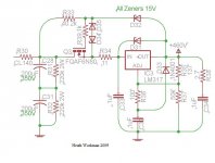
I have cobbled a concept schematic together.
No values on components yet, just wanted to check if I was on the right path. I have basically just copied the front end of "El Cheapo". Mosfet source followers to 7591.
A few questions. The 7591 data sheet lists the drive requirements for ultralinear as bias of -20.5 volts and peak AF grid to grid voltage of 41 volts. Does this require that the mosfet must be able to swing 41 volts peak to peak, requiring it to have a power supply of +/- 20.5 volts, plus a buffer? In other words, if I have to supply a -20.5 volt bias supply, can I use this also to supply the -ive supply for the mosfet and then just have to supply a +20.5 volt supply?
Sorry for the stupid questions, have done a bunch of reading but much of it is yet to sink in!
Answers to this guidance will obviously then guide the power supply design...
Thanks again guys, appreciate the patience and help.
Cheers,
Chris
I will leave the power supply issues for a later post...
Sorry I did not get the opportunity to talk on the phone while in LA Eli, was busy with work matters.
I have cobbled a concept schematic together.
An externally hosted image should be here but it was not working when we last tested it.
No values on components yet, just wanted to check if I was on the right path. I have basically just copied the front end of "El Cheapo". Mosfet source followers to 7591.
A few questions. The 7591 data sheet lists the drive requirements for ultralinear as bias of -20.5 volts and peak AF grid to grid voltage of 41 volts. Does this require that the mosfet must be able to swing 41 volts peak to peak, requiring it to have a power supply of +/- 20.5 volts, plus a buffer? In other words, if I have to supply a -20.5 volt bias supply, can I use this also to supply the -ive supply for the mosfet and then just have to supply a +20.5 volt supply?
Sorry for the stupid questions, have done a bunch of reading but much of it is yet to sink in!
Answers to this guidance will obviously then guide the power supply design...
Thanks again guys, appreciate the patience and help.
Cheers,
Chris
- Status
- This old topic is closed. If you want to reopen this topic, contact a moderator using the "Report Post" button.
- Home
- Amplifiers
- Tubes / Valves
- 6L6GC AB2 Amp