So should I be worried about the brief high voltage on g2?
Maybe it's not an issue if you're not exceeding the 6 watt dissipation rating.
What about inserting a thermistor in the B+ rail?
I wonder how this amp would sound with the new discovered "crazy drive" connection of the powertube and some local feedback
I'm hoping to try this at some point, but I think I'll try bird's version first.
jeff
I wonder how this amp would sound with the new discovered "crazy drive" connection of the powertube and some local feedback
I will leave this amp how it is and most likely try crazy drive with the 6HJ5 for a different project. I bought enough to play with and might think about ordering some more along with some more 12HL7's.
Maybe it's not an issue if you're not exceeding the 6 watt dissipation rating.
That's what I am thinking
In Raytheon's datasheet it states that g2 is rated for 12watts "warm up surge" dissipation, specified time of surge states for 15 seconds. I am probably over thinking things at this point and the 6HJ5 seems like a very rugged tube.
Attachments
Yes you are correct in that the 6HJ5 was used in the Futterman H3 OTL amp. I have never had the chance to hear one of those amps. Thanks for the interest shown in my build. I couldn't have done it without all the help from the sweep tube gurus lurking around these parts")
I should have a full schematic ready to post in the next couple days.
Would you be so kind to post the full schematic. Thank you in advance
Would you be so kind to post the full schematic. Thank you in advance
Hi, thanks for the interest in my amp. I am glad you asked for the schematic because I forgot to draw one up for the thread. It will be added soon, sorry for the delay.
I get sidetracked easily lol.
I went back to an RC arrangement on the cathode of the parallel 6N7 triodes. The RC is paralleled with a trimpot arrangement in order to adjust plate voltage of the stage. The trimpot has a fixed resistor in series in order to prevent a dead short to ground when the pot was turned all the way in one direction. I did this because the first handful of 6N7's I popped in there all would settle close enough to around 170v so I didn't see an issue with the LED bias. BUT I was rolling some more tubes and doing more testing lately and found that some of the Tung-sol's I had were all over the place, one channel would have Va=150 and the other channel 175. I decided I can't be a total cheapskate, the $.10 LED's were a good idea and worked well but being able to adjust things is worth the extra few bucks. I actually increased the plate voltage up to 200v and am finding I like the sound better. Most specimens I have I can get an operating range from 140v to 215v @ 8mA with the new bias mod. No fancy R's or C's once again, just some Nichicon 100uF, 35v lytic's and carbon film resistors.
Good thing I didn't post the "finished schematic", it would have already been revised.
BTW I don't use schematic programs but feel like giving one a try to make things look professional. I have Linux Ubuntu for an OS and am looking for something free. I think I have the free version of Eagle already so maybe I will start there if it's any good.
I am a paper and pencil dude, I only put circuits into the computer for simulations, sometimes I screen capture the sim program and upload the picture file but for this I want it to look like a normal schematic done with a program. Eagle can even put things to a PCB layout so it will be a good thing to learn, I believe the free version limits the size PCB board you can make.
Eagle is very good but the free version has some pretty annoying limits.
I had struck out with Eagle and gEDA in the past and recently took up KiCAD. It is surprisingly easy to use. Open source, and CERN (the large hadron collider people) use it and contribute code.
I just pulled this board out of the water and peeled the paper off of it. Designed in KiCAD and spiffed up in Inkscape. It's upgrade boards to convert Stax SRD-7 energizers to SRD-7 Mk2 to support a wider range of earspeakers:

Last edited:
Nothing wrong with a decent hand drawn sketch.
I agree
But I like to think this old dog can learn new tricks. I can microwave a cellphone too.I just downloaded KiCAD and look forward to trying it out later this evening.
That board looks great! I like the 7up logo, that must have been added in Inkscape maybe?
Thanks!
Yeah. I used the plot feature in kicad to get an svg of the layout, then used inkscape to add the logo and text, and repeat it to fit four across. I have 20+ sheets of copper clad fr4 roughly that size.
Then exported as pdf, printed on HP glossy brochure paper, and ran it several times through a hot laminator on the board - prepped by sanding it a bit with 800 grit and then cleaning with acetone.
After a short soak the paper came off in a single piece.
.:Sent by pneumatic tubes

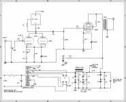
Hi guys, sorry for the delay. I have made some changes like putting an RC network at the cathode of the driver stage to adjust the plate voltage to ~200v, I had better results with this OP. Adjustment is made by a 1k adjustment pot at the cathode.
Here is a schematic finally, please let me know if you see any gross errors.
Thank you JosM for getting my back with that schematic!!! You posted one before me
Here is a schematic finally, please let me know if you see any gross errors.
Thank you JosM for getting my back with that schematic!!! You posted one before me
Attachments
Last edited:
Thank you JosM for getting my back with that schematic!!! You posted one before me
Thank you both for the schematics.
troll alert. i have strongly considered a PP version with these output tubes. worthwhile?
Apparently, several were build using Pete's "Big Red Board" as the platform for a high power PP amp. There is some info buried in the big thread:
http://www.diyaudio.com/forums/tubes-valves/151206-posted-new-p-p-power-amp-design.html
jeff
- Home
- Amplifiers
- Tubes / Valves
- 6HJ5 SET