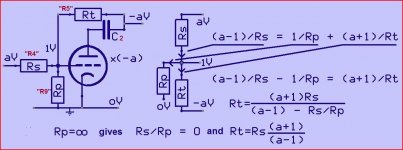
There is nothing "floating", you need a very very high gain for that.Here the "floating" point carry a voltage (AC) used by the tube to produce the same voltage of the first tube, but 180° out of phase.This resistor, in line with the voltage divider between both anodes, appears to be essential with the original Floating Paraphase idea. Their value shold be much smaller w.r.t. the following stage's grid leak resistors, though.
Best regards!
The R9 loads the circuit that provide the grid AC, effectively making the inverting stage gain smaller.
Mona
Attachments
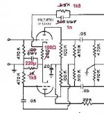
No, it is the shared cathode. A true floating paraphase inverter can have two totally different tubes which cannot be the case if you have a shared cathode. Be aware that a cathode that is not bypassed has negative feedback, the 12AX7 drops from approx 40x amplification to approx 14.2x according to my calculation. The drawback is that when you do not bypass the cathode-heater leakage can give hum so you have to use a tube with little leakage. On another note: the 6SN7 is about the most linear double triode that you can find, I like that tube a lot.
edit: I do not like fixed bias. That is fine if you want maximum power output but you run the risk of shortened tube life and higher distortion, especially if the tubes are not well balanced. I cannot find the article anymore (but am certain about it since I queried the Audio Note setup) but for the least distortion Mullard recommended to bias the output PP a bit more towards class B than the normal AB recommended and to use individual cathode resistors.
Forgot to mention that you will loose the ability to adjust the balance which means that you cannot adjust for minimum distortion at the output.
That's no good.They put an attenuator before the phase inverter to compensate for it's gain.But the gain is not a constant, bad compensation.
Mona
There is nothing "floating", you need a very very high gain for that.Here the "floating" point carry a voltage (AC) used by the tube to produce the same voltage of the first tube, but 180° out of phase.
The R9 loads the circuit that provide the grid AC, effectively making the inverting stage gain smaller.
Mona
Erm, what did Norman Crowhurst tell us in his papers shown in #6, especially in pics 1 and 2?
Best regards!
Well, he agrees with what i said, it becomes floating with very high gain of the inverting stage.But with tubes, ~70x with ECC83, we are far away from very high.The resistor grid-ground makes a difference, see my calculation.Erm, what did Norman Crowhurst tell us in his papers shown in #6, especially in pics 1 and 2?
Best regards!
Mona
..t. What is the reason for different bias points for the two halves of the AX7?
What difference?
The added 200r in one cathode? Big deal.
Also note that there is 3.3K to ground (through OT) on the high end of that 200r. It may not be so very different after all. However I'm sure another 200r is not going to "mis-bias" the triode-- a wide range will work.
If you don't like that, a simple solution...Thank you for joining in. Interesting circuit. What is the reason for different bias points for the two halves of the AX7?
Mona
Attachments
")
- Status
- This old topic is closed. If you want to reopen this topic, contact a moderator using the "Report Post" button.
- Home
- Amplifiers
- Tubes / Valves
- 6EM7 Floating Paraphase (I know humor me please)