I do have the cathode tied to the heaters.
I saw the arc/ flash a few seconds after I turned on the amp.
It definitely looked like an arc. I did not know about filament flash. This is the first time I have asked or mentioned this. I hope no one thinks I am the person mentioned previously. I understand the frustration of someone not listening to advise or explanations.
I was questioning about it as I wanted to be sure it was fine... plus I plan on making a higher voltage power supply, and I was wondering if transmitter tubes would be better suited.
I thank you all for your information and I hope no one feels this thread is a waste of time.
Last edited:
If the 6de4s were run in parallel it likely wouldn't happen. They aren't made to be run in series like they are here so the lack of controlled warm-up can cause anomolies. An ntc thermistor in series with the string might stop it from flashing.
We've all got to learn sometime!
We've all got to learn sometime!
Hi!
I am surprised nobody has asked the obvious thing to check:
Did you run a PSUD simulation? 40uF is an awful lot of capacitance at this voltage and you might exceed the max peak current when charging up the caps.
Another possibility is exceeding heater/cathode voltages
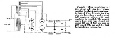
You should post an exact schematic showing what you did and which tube arced. A bridge has 4 cathodes. Only 2 of them are connected together. Two are on AC potential. If you connected the heater string to B+ output, the two diodes with their cathodes on AC will exceed heater/cathode voltage ratings.
If there was an arc once it will appear again and typically increasingly often. Most likely that tube is already partially damaged and will quickly degrade.
Best regards
Thomas
I am surprised nobody has asked the obvious thing to check:
Did you run a PSUD simulation? 40uF is an awful lot of capacitance at this voltage and you might exceed the max peak current when charging up the caps.
Another possibility is exceeding heater/cathode voltages
I do have the cathode tied to the heaters.
You should post an exact schematic showing what you did and which tube arced. A bridge has 4 cathodes. Only 2 of them are connected together. Two are on AC potential. If you connected the heater string to B+ output, the two diodes with their cathodes on AC will exceed heater/cathode voltage ratings.
If there was an arc once it will appear again and typically increasingly often. Most likely that tube is already partially damaged and will quickly degrade.
Best regards
Thomas
I do have the cathode tied to the heaters.
Could be an issue..
I saw the arc/ flash a few seconds after I turned on the amp. It definitely looked like an arc.
Heater flash appears immediately as power is applied, and dies off just as quickly. It is purely due to heater incandescence. If you are seeing a flash / arc several seconds later, that's a true arc striking up inside of the envelope.
Hi!
I am surprised nobody has asked the obvious thing to check:
Did you run a PSUD simulation? 40uF is an awful lot of capacitance at this voltage and you might exceed the max peak current when charging up the caps.
You might want to check posts #4 and #6 in this thread. Simulations weren't mentioned, but concerns about the input capacitance definitely were. This is not how these particular tubes were intended to be used, they're damper diodes not power rectifiers. Not to say they can't be re-purposed, as a number of other TV types have been, but we shouldn't be too surprised if odd things happen.
Last edited:
Could be an issue..
it is, runnig off a single 24 volts filament supply, i can not imagine how it will work...
Heater flash appears immediately as power is applied, and dies off just as quickly. It is purely due to heater incandescence. If you are seeing a flash / arc several seconds later, that's a true arc striking up inside of the envelope.
Marantz used this tube in one of their amps...model 2
it is, runnig off a single 24 volts filament supply, i can not imagine how it will work...
I'd tend to agree, especially after seeing the ARRL implementation you posted.
Marantz used this tube in one of their amps...model 2
A pair of them in full-wave, I see that now. Thanks for pointing it out, it's a type I've never seen used in vintage audio.
a 100 volt dc rating for heater cathode, individual filament windings are
mandatory imho, and these filament windings to have at least a 1kv insulation
between them...
tbh, i never bothered with design softwares, just curious though
can PSU2 detect design errors?
mandatory imho, and these filament windings to have at least a 1kv insulation
between them...
I am surprised nobody has asked the obvious thing to check:
Did you run a PSUD simulation? 40uF is an awful lot of capacitance at this voltage
and you might exceed the max peak current when charging up the caps.
tbh, i never bothered with design softwares, just curious though
can PSU2 detect design errors?
> at least three filament windings
That's directly heated filament cathodes. This simply can not work without at least three filament circuits.
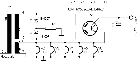
6DE4 has indirect heat with heater-cathode insulation. In many tubes this insulation is good for a few hundred volts. 6DE4 is odd because it is rated for cathode _900_V positive of heater. A TV Damper is intended to live with its cathode at 250DC-450VDC while (preferably) sharing a heater supply with all the other tube heaters in the set (referenced to 0V or some low voltage). So groundy heater circuit, 480VAC = 670V DC, he's not at the 900V rating. It "should" work OK with all heaters on the same supply, if that supply is referenced to 0V.
That's directly heated filament cathodes. This simply can not work without at least three filament circuits.
6DE4 has indirect heat with heater-cathode insulation. In many tubes this insulation is good for a few hundred volts. 6DE4 is odd because it is rated for cathode _900_V positive of heater. A TV Damper is intended to live with its cathode at 250DC-450VDC while (preferably) sharing a heater supply with all the other tube heaters in the set (referenced to 0V or some low voltage). So groundy heater circuit, 480VAC = 670V DC, he's not at the 900V rating. It "should" work OK with all heaters on the same supply, if that supply is referenced to 0V.
Hi!
PRR is right, the example from ARRL is with directly heated rectifiers which of course need 3 windings. With indirectly heated diodes you can use one common winding if heater/cathode voltage ratings are not exceeded.
Read the data sheet carefully this is the rating for heater positive to cathode and it is for DC. Heater negative to cathode is 900VDC max. If the heaters are referenced to gorund and not to B+ these ratings will not be exceeded at these voltages
It will detect if peak inverse voltage or current limits are exceeded. It will not detect heater to cathode voltage errors since that is not modelled.
Best regards
Thomas
PRR is right, the example from ARRL is with directly heated rectifiers which of course need 3 windings. With indirectly heated diodes you can use one common winding if heater/cathode voltage ratings are not exceeded.
a 100 volt dc rating for heater cathode, individual filament windings are
mandatory imho, and these filament windings to have at least a 1kv insulation
between them...
Read the data sheet carefully this is the rating for heater positive to cathode and it is for DC. Heater negative to cathode is 900VDC max. If the heaters are referenced to gorund and not to B+ these ratings will not be exceeded at these voltages
tbh, i never bothered with design softwares, just curious though can PSU2 detect design errors?
It will detect if peak inverse voltage or current limits are exceeded. It will not detect heater to cathode voltage errors since that is not modelled.
Best regards
Thomas
Hi!
For voltages like those involved here there is no need for separate heater windings. TV dampers have a low rating for heater positive to cathode but the 900V rating for heater negative to cathode gives enough room to operate with a single heater winding. I am using TV dampers like that since 20 years and have built well over 100 power supplies this way. Only for higher voltages as for example in 211 or 845 amps separate heater windings are needed in a bridge configuration
For voltages like those involved here there is no need for separate heater windings. TV dampers have a low rating for heater positive to cathode but the 900V rating for heater negative to cathode gives enough room to operate with a single heater winding. I am using TV dampers like that since 20 years and have built well over 100 power supplies this way. Only for higher voltages as for example in 211 or 845 amps separate heater windings are needed in a bridge configuration
I am with Thomas - never build a power supply with big capacitors, without checking the startup conditions using PSUD2.
It took me about 2 minutes to do this job for you! Please download the attached archive file, if you want to try it yourself.
I have assumed that your transformer has effective windings-resistance of about 100Ω: R(sec) + R(pri, referred). You have to measure these values and add to PSUD2 to get an accurate picture.
It shows that the continuous peak current rating (IFRM) is exceeded during the first 0.5 second or so.
Violating IFRM during the time that it warms up is even worse than during normal run-time, because the cathode of the rectifier is only half-warm and cannot give full current capacity. And when there has been arc-overs like this, the cathode will be damaged, and further arc-overs are more likely.
How to address the problem?
It will be necessary to check the winding resistances as noted above, and re-run PSUD2.
Adding chokes does not necessarily fix the problem - they will saturate before limiting the current adequately, unless they are physically very large..
choices:
1. add resistance in series with the trafo winding, to limit startup current. Be sure to calculate the power burned in these resistors, and use flameproof types.
2. change caps to smaller values, add chokes for filtering effect.
3. If you really need the big capacitors, use Silicon-Carbide (SiC) rectifiers. These work very well, and do not suffer the big reverse-recovery current-pulses seen with other solid state diodes.
Attachments
Hi!
For voltages like those involved here there is no need for separate heater windings. TV dampers have a low rating for heater positive to cathode but the 900V rating for heater negative to cathode gives enough room to operate with a single heater winding. I am using TV dampers like that since 20 years and have built well over 100 power supplies this way. Only for higher voltages as for example in 211 or 845 amps separate heater windings are needed in a bridge configuration
better safe than sorry.....
i am not using dampers in a bridge so i might never know....
i am a hybrid rectifier user....
better safe than sorry.....
sure, but why waste resources if really not necessary.
Of course you can use 3 windings but these are rarely available.
As mentioned 20 years of actual experience in 100 and more PSUs are proof enough that those ratings in the datasheet can be trusted.
Rather address the real problem here and that is the capacitance.
And if the OP connected the heater winding to the wrong voltage potential that needs to be corrected as well.
Thomas
Hi!
I see no reason to mistrust the data sheet which clearly states 900VDC.
I am all for safety and usually stay well below max limits.
BTW in the example you posted the heater is referenced to ground as well and not connected to the cathode and that although the 6X4 has only half the rating of the 6DE4 for heater negative to cathode...
BR
Thomas
Thank you everyone.
I did simulations... many of them using psud2.
However, I had it set up to start 10 second after running. Not sure why I did that...
I will run it again. I will reference the heaters to ground.... And use a smaller input cap.
I have been recently using math formulas to find out how much capacitance is needed and it's not as much as I thought. I'm leaving the mindset of many that more capacitance is better...just use what is needed.
The transformer is a control transformer, and has less than a 100ohm resistance....
So...there seems to be some *** that can be fixed...and I will do so. This amp has been running for over a year, and has been played upto 12+ hrs. and day. The owner is retired.
- Status
- This old topic is closed. If you want to reopen this topic, contact a moderator using the "Report Post" button.
- Home
- Amplifiers
- Tubes / Valves
- 6DE4 Flash