Rightmark Audio Analyzer tests
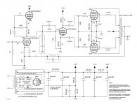
I "fixed" the feedback circuit that I so royally screwed up previously.
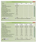
I finally got the equipment needed to do testing of the amp with Rightmark Audio Analyzer. I have attached the results below.
The test setup is an HP TX1000, 64-bit Windows 7, with a Behringer UCA222 USB sound card. I used a Behringer DI100 direct box for connection of the speaker terminals back to the sound card input. I have also included the loopback test baseline results in the attachment. That is, UCA222 output to DI100 input, DI100 output to sound card input.
RMAA wants the signal level for testing at -1.0dB. I was able to get the signal level adjusted to -1.1dB for the tests. I did not have the compensation circuit connected for the tests. After testing, the compensation doesn't seem to be necessary. The amount of feedback used for these tests was calculated to be about -4 to -5dB.
I measured right at 1mV AC on the speaker terminals with no input signal. The amp is dead quiet.
I ran the tests several times with precisely the same results. The amp was on for about 1 hour before I tested.
I'm not sure at this time why the left channel is so much different than the right. Maybe a difference in the output transformers. I'll swap the tubes around and see if that makes a difference.
I'm very pleased with these results, although I could use a better soundcard for testing than the UCA222. The Realtek HD Audio built-in card on my TX1000 is actually worse than the UCA222 when tested with RMAA.
Bottom line though, the amp sounds fantastic.
I "fixed" the feedback circuit that I so royally screwed up previously.
I finally got the equipment needed to do testing of the amp with Rightmark Audio Analyzer. I have attached the results below.
The test setup is an HP TX1000, 64-bit Windows 7, with a Behringer UCA222 USB sound card. I used a Behringer DI100 direct box for connection of the speaker terminals back to the sound card input. I have also included the loopback test baseline results in the attachment. That is, UCA222 output to DI100 input, DI100 output to sound card input.
RMAA wants the signal level for testing at -1.0dB. I was able to get the signal level adjusted to -1.1dB for the tests. I did not have the compensation circuit connected for the tests. After testing, the compensation doesn't seem to be necessary. The amount of feedback used for these tests was calculated to be about -4 to -5dB.
I measured right at 1mV AC on the speaker terminals with no input signal. The amp is dead quiet.
I ran the tests several times with precisely the same results. The amp was on for about 1 hour before I tested.
I'm not sure at this time why the left channel is so much different than the right. Maybe a difference in the output transformers. I'll swap the tubes around and see if that makes a difference.
I'm very pleased with these results, although I could use a better soundcard for testing than the UCA222. The Realtek HD Audio built-in card on my TX1000 is actually worse than the UCA222 when tested with RMAA.
Bottom line though, the amp sounds fantastic.
Attachments
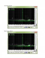
The channel difference could be due to a slight mismatch in output valves. If you can separate into odd and even order distortion this might help.
Here are the THD plots that correspond to columns B & D from the previous post of the RMAA test. The left channel of the soundcard was used for testing both channels of the amplifier. The right channel shown on the THD plots was just looped through the soundcard.
Attachments
- Status
- This old topic is closed. If you want to reopen this topic, contact a moderator using the "Report Post" button.