Have you heard any of the Trancendent OTL's?
Yes, I have heard the T-8 and the T-16 and they are quite good.
Among other OTL's I have heard are Graaf GM-20 and GM-100, Silvaweld OTL 100S 2x40W, Silvaweld mono OTL 100W Tenor 15W, Mactone M-8V, Audioprofessor, (sold as kit in Japan), Topstone I-3 and I-4, (sold as kits or assembled in Japan), Atmasphere M-60 and San-Ei, there are more but these are the ones I remember. I was living in Japan until end of last year and my office where only one train stop from Akihabara so I could go there even during lunch time, there are many stores offering a wide variety of tube amplifiers, the ones with transformers are to many to list.
I think that the best conventional transformer coupled amp I have heard so far is also from San-Ei it was a push-pull with KT88, unfortunately San-Ei ceased to exist as a shop a few years ago and now they only offer a limited selection of models as kits through male order.
Regards Hans
Hi Patrick,
I have used them only in the tail of differential pairs, where they work well and seem to have minimal impact on the sound. I am pretty old school when it comes to tube amplifier circuits, I don't like hollow state mixed with solid state. Triodes with ccs loading have transfer functions in some instances that no longer look very triode-like, i.e. harmonic spectra is predominantly odd order, not even (mostly 2nd) as found in conventional rc or transformer coupled triode amplifier circuits. See Morgan Jones for further discussion of this phenomena.. I have always found in the end that simplicity pays dividends when it comes to sound quality..
Kevin
I agree with Kevin that caution is indicated when using solid-state CCSs in the plate circuit of triodes. I worry as much about the non-linear solid-state capacitances causing frequency intermodulation as I do about the resistive component of CCS impedance. Gary Pimm's CCS designs seem to have driven the capacitance values to extemely low numbers however.
I don't like hollow state mixed with solid state.
Dear Kevin,
I am very interest of this topic. I used them in the tail of differential pairs also. Please direct me to Morgan Jones' Phenomena discussion.
Due to my poor English understanding, please explain what is the meaning of "hollow state".
Thank you.
Dear Brain,
Frequency intermodulation is a very interesting topic too. Please let me study Gary Pimm's CCS design and share your experiences to me if possible.
Regards
Patrick
Hi Pat,
Morgan Jones is the author of a series of books on building tube hifi, you want the third edition of his valve amplifier book which you should be able to find on amazon.com.
Hollow state is a humorous label many apply to anything pertaining to tubes. It refers to the fact that electrons are flowing through empty space (vacuum)
Kevin
Pat,
Let me add my enthusiastic recommendation for buying Morgan Jones' excellent book.
As for Gary Pimm's fine CCS designs, take a look here:
Gary Pimm's site (CCSs)
As for the frequency modulation effects, I've been slowly working on the research for a paper on the topic. Stay tuned, but don't hold your breath
Let me add my enthusiastic recommendation for buying Morgan Jones' excellent book.
I'll third that. MJ's book convinced me to give CCS circuits a second chance after some unsatisfactory experiences in the past. He was right and I've never looked back. If you want to do tubes, it's the best $50 you can spend.
For what it’s worth, I have a general guideline I use when considering CCSs for tube circuits: CCSs in the cathode circuit are easier, less critical, and less injurious to sound than CCSs as plate loads. As a result I would consider simpler solid-state CCSs at the cathode than I would for the plates. Why? The cathode resistance is lower than the plate resistance, usually by about a factor of mu or so. Non-linearities in the CCS impedance (in both resistance and capacitance) will therefore have less effect on the cathode end than on the plate end. CCSs in the plate circuit must have much higher resistance and less capacitance to avoid becoming factors adversely affecting gain and distortion.
Of course, CCSs in cathodes are used for different design purposes than CCSs used in plate circuits, so I’m not suggesting that you have a choice of either using a cathode CCS or a plate CCS for any given tube stage. What I am saying is that if you want to use a CCS in the plate circuit, more care must be taken, about “mu times” more care, if you want to think of it that way. I’ve seen too many hybrid designs with overly simple solid state current sources used as plate loads. In the past I have favored only tube CCSs in the plate, such as true pentode current sources or mu stage designs with triodes. Recently, Gary Pimm’s various designs have pushed the CCS resistance to new heights and have driven capacitance to very low levels, and listeners have been very receptive. While I haven’t built one of his CCSs yet, I can believe the favorable reports.
Examples of CCSs in the cathode circuit are as the tail of a differential pair, as a replacement of the cathode resistor for a cathode follower, or as a bypassed CCS used to set the DC bias of any common cathode stage. Here relatively simpler solid state implementations can usually work pretty well.
Just my view…
Dear Friends,
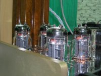
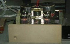
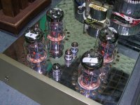
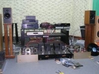
Thanks for my friend Wood's assistances the job finally came out. It is a very good Christmas present for me although it needs further modification. The schematic had changed a lot from the original design and I will post it later. The photos were took in Wood¡¦s studio.
Happy New Year,
Patrick
PS. I don't know how to include the images in text. Can anybody help?
Attachments
Happy new year Patrick!, good to hear that you made it work!
The measurements look interesting but it is difficult to read the scales, is it correct that distortion reach 1% at about 85W?
Do you know why distortion increases so much at lower frequencies? have you deliberatly limited the open loop frequency response on the low frequency side?
How much feedback do you use? and what is the anode voltage to the output tubes?
Regards Hans
Happy new year Hans,
Thanks for your prompt response.
1KHZ distortion data as following:
0.1W - 0.28%
0.5W - 0.18
1W - 0.175
2W - 0.21
5W - 0.3
10W - 0.48
20W - 0.7
30W - 0.87
40W - 0.97
50W - 1.1 (max. unclip output)
60W - 1.45
75W - 2.3
85W - 5.5
(I found that the voltage swing of driver output were not enough)
No, I had not limited the open loop frequency on the low side, please tell me why?
Gobal FB is 6dB and in-state FB is 10dB. Anode voltage 145V (intend to reduce to 130V), current 300mA (intend to increase to 400mA).
Regard
Patrick
Hi Patrick,
Anode voltage is lower than I expected, I am using around 150V in my new OTL using 4 tubes and getting around 80W at clipping, I will increase to 160V and expect to get 100W, current is 200mA per tube.
The reason why I thought you had reduced the open loop response is that the distortion is increasing for lower frequencies which is not what I would have expected as there would be high open loop gain and therefore as much feedback as for mid band frequencies. Do you know why it behaves like that?
Regards Hans
- Status
- This old topic is closed. If you want to reopen this topic, contact a moderator using the "Report Post" button.
- Home
- Amplifiers
- Tubes / Valves
- 6C33 Circlotron