Indeed! He uses 110V:24V+24V toroidal transformer for input stage and 110V+110V : 6V for opt. Fascinating! Why toroidal? Is there a benefit for using toroidal? This is new to me.He is a fan (sorta) of mains torroidals used as opts and for interstage duties
Thanks
Toroidals have extremely high bandwidth. Mine give response out to about 60khz without droop. The bottom end on mains toroidals can be a little compromised if they are not run with a low impedance output stage, hence the use of Schade feedback.
The main advantage beyond bandwidth, if the lack of any sort of gap which minimises hysteresis in the core. The sonic effect of this is low amounts signal blurring at subwatt levels of output - the main area where PP output stages suffer over SE output stages. The down side of this is that they are very intolerant of standing DC and this is why I always use CCS in the cathode to maintain absolute current balance down to less than 1mA. Since this is only possible when running in class A, I use the opportunity to run the output stage as fully differential, and hence the bypass caps on the cathodes run to each other rather than ground. The 1meg resistor at the junction is to bleed leakage current to ground and keep the caps biased.
In the case of input toroidals, why do I use them ? They work well and they are cheap. Generally I find my designs have to much gain for my needs, so I can get away with stepping down the input signal which helps to extend bandwidth. Any reasonable quality input transformer can be substituted. The input transformer could be eliminated, but this would require the addition of an input coupling cap, and would reduce gain and probably not be as balanced. I find the small cost of a pair of 10VA mains toroidals to be worth it.
Shoog
Last edited:
Since this is only possible when running in class A, I use the opportunity to run the output stage as fully differential, and hence the bypass caps on the cathodes run to each other rather than ground. The 1meg resistor at the junction is to bleed leakage current to ground and keep the caps biased.
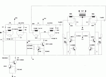
I recently found the schem. shown below. What do you think of the CCS implementation on the output stage?
Jeff
Attachments
The CCS's themselves look good, but remember that this approach always restricts operation to class A. Since you are running class A why not go differential as in my design ?
The big electro caps are already in the signal path, but running therm back to back would helps to reduce their distortion. Sound wise you should expect a cleaner sound. The only slight consideration is that the caps need to be doubled as they are in series and so their effective value is halved.
Shoog
One thing to consider if using those CCS's is that the zeners are essential. I found out the hard way that because of the direct coupling - on switch on the cathodes can have the full B+ of 300V across them which will fry anything less than a 500V rated component instantly. I am using the 900V IXY chips as a result. The zeners will absorb this switch on surge.
A time delay on the +B will help protect the output valves which otherwise are asked to conduct hard with cold cathodes - not good
Shoog
A time delay on the +B will help protect the output valves which otherwise are asked to conduct hard with cold cathodes - not good
Shoog
That works for me. Thanks.In the case of input toroidals, why do I use them ? They work well and they are cheap.
Would these work?
Triad Toroidal VPT48-520 25 Primary 115v secondary In series: 48V CT @ 0.52A; In parallel: 24V @ 1.04A; Regulation 12.0%
1. Maximum Power: 25VA
2. Input Voltage: Series: 230VAC, 50/60Hz
Parallel: 115VAC, 50/60Hz
3. Output Voltage: Series: 48VAC CT @ 0.52A
Parallel: 24.0VAC @ 1.04A
So I would need two of these?
Thanks again
That works for me. Thanks.
Would these work?
Triad Toroidal VPT48-520 25 Primary 115v secondary In series: 48V CT @ 0.52A; In parallel: 24V @ 1.04A; Regulation 12.0%
1. Maximum Power: 25VA
2. Input Voltage: Series: 230VAC, 50/60Hz
Parallel: 115VAC, 50/60Hz
3. Output Voltage: Series: 48VAC CT @ 0.52A
Parallel: 24.0VAC @ 1.04A
So I would need two of these?
Thanks again
That would do OK, but bare in mind that that represents a 4:1 voltage step down. That would be fine for me, but not for everyone. A higher voltage secondary might be better. Some places do small 110+110:55V+55V which is a step down of 2:1+1. Yes you need two for two channels.
My understanding is that this arrangement will only work in pure class A.
Shoog
Last edited:
Since you are running class A why not go differential as in my design ?
Thanks, I may just do that.

Jeff
- Status
- This old topic is closed. If you want to reopen this topic, contact a moderator using the "Report Post" button.
- Home
- Amplifiers
- Tubes / Valves
- 6bg6 and 8k opt power amp project