I've found my transformer, a Hammond potted toroid 240 volts secondary at .94 amp. Loaded I should have about 230 volts DC.
I'm thinking of a bias point of 100ma at 105 volts which will give me a grid voltage of -40. I did the calculations and came up with a plate resistance of 353 ohms?
131-85/170-40=46/130= 353?
Based on that I'm looking at an Edcor 25 watt 1.6k output transformer.
I'm thinking of a bias point of 100ma at 105 volts which will give me a grid voltage of -40. I did the calculations and came up with a plate resistance of 353 ohms?
131-85/170-40=46/130= 353?
Based on that I'm looking at an Edcor 25 watt 1.6k output transformer.
Too late to edit/delete so scratch the power transformer. I'm going to need more voltage. If I use a parafeed cap at the center tap of the output transformer there will be no DC on the primary. But there will be no resistance between the plate and ground through the power supply. So I will need plate resistors to get any gain won't I? Hadn't thought about that until I was almost asleep just now.
Last edited:
I'm thinking of a bias point of 100ma at 105 volts which will give me a grid voltage of -40.
I'm going to need more voltage.
I told you this a week ago. With 105 V, 100 mA and 1k6 OPT you will get 2 W from one 6AS7G as PP.
Have you done any simulations or drawn loadlines ? These can be very useful and informative.
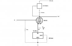
First let me say thanks for all the help I've received so far. I've wanted to build a powerful all triode amp for a few years now and I think this is going to be it. I've received some help off the thread via PM that has lead me to the attached schematic snippet. I would appreciate it if anyone could point out any obvious errors.
Attachments
It is an autoformer. To be precise, an old type of autoformer that's almost certainly not compliant to current CE regulations anymore (EN61558). You cant'have that kind of output plug mounted in that way, unless they developed some very special designs in the internal parts. Unlikely, given the price and the seller. The "shipping weight" with packing materials is rated 7 lbs (about 3 Kg). The weight of a good EN61558 compliant 500VA autoformer without any packing, cable or connector starts at about 4 Kg. My experience with cheap vstep down transformers is that they have high losses, bad regulation and become hot even without any applied load.
Edit: this was a reply to post #50. For some reasons my browser hid the last part of this thread until I posted.
Edit: this was a reply to post #50. For some reasons my browser hid the last part of this thread until I posted.
Last edited:
I'm really green when it comes to SS devices so you may be right. As I understand it a CCS (either flavor) is very good at ripple rejection. From that I assume they also reject signal as well, since audio signal is AC. I was assuming that bracketing the tube would leave no outlet for the signal current except the output therefor maximizing gain? Plus, using the parafeed cap will be a short to ground for the signal creating a path towards the output and the CCS's will encourage that won't they?
As for the placement of the parafeed cap placing it between the plates and the primary or the centertap and ground would be easy to change. So this may work as the experiment Broskie mentioned.
Thanks for the mention of Triad. I've used their chokes for years. I'll check into them. It seems those chokes are no longer in production. They have been removed from the Triad website.
To answer your inital question: Yes I heard a 6as7g-amp: The baldur 200 as well as an PP amp a friend has build. He used "only" 6 pcs/12 triodes per channel. Very classical PP-Build, Cathode-Biased without caps, 6sn7/6bl7 driver/phase-splitter, all RC-coupled. Sounds great.
I've decided to use Pete Millett's uniamp as a front end. Its a two stage using 6SN7 in a differential amplifier. I've used it to drive 2A3 and AD1 push pull amps. It swings 235 volts peak to peak. Its at heart two long tail pairs so a pair of CCS in the tails should lower the distortion even further. I have a box of 6SN7 and all the passives in hand.
Its at heart two long tail pairs so a pair of CCS in the tails should lower the distortion even further.
Unfortunately this is not happening.
The 6AS7G PP output stage create quite high (~4%) THD.
One very often used method to reduce THD is to use distortion cancelling, which is to bias the driver stage to create similar THD spectrum which is then compensating the THD of the output stage.
If this is done properly, the overall THD drops from 4% to below 1%.
So if you build a Hi-End driver with minimum distortion, you will get a non Hifi 6AS7G amplifier.
I've decided to use Pete Millett's uniamp as a front end. Its a two stage using 6SN7 in a differential amplifier. I've used it to drive 2A3 and AD1 push pull amps. It swings 235 volts peak to peak. Its at heart two long tail pairs so a pair of CCS in the tails should lower the distortion even further. I have a box of 6SN7 and all the passives in hand.
Found my 2-yr old sketch, I was considering building one on 6080 too but dropped the idea once realized how much complication it is. Most likely not enough driving swing, and, as Shoog pointed out the halves are far from being matched, so those would be the considerations. Might be silly, or might. .. work /give you a hint.
An externally hosted image should be here but it was not working when we last tested it.
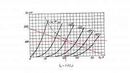
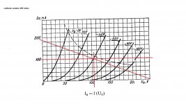
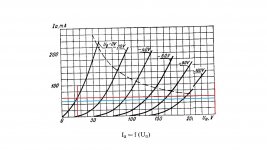
Thanks Shef. I've been looking at the load lines and I've included two examples. One cathode bias and one with dual CCS, Source for plate and sink for cathode. First off the grid voltage for 6N13S is -40 not the -125 for 6AS7. At Shoog's suggestion I plan to use a current source for each plate and a sink for each cathode. That should, if I'm right, provide the best rejection on both ends and should minimize the difference between triode halves? With cathode bias the grid voltage would be -40 at the bias point. With the CCS load line to stay under the 13 watt dissipation limit I would need to keep the plate current under 52ma for 250 volts of B+ or 60ma and just not drive the tube so hard. Or drop the B+ to 215 volts and up the current to 60ma. Is there any way to know or guess what would be the best way to go?
Attachments
Shef, I've been looking at your drawing and have some questions. I see you're taking the drive from the cathodes of the upper tube but it seems that would limit voltage swing or am I wrong? And does the lower 12AT7 function as a voltage amplifier and a phase splitter? And is the right grid of lower 12AT7 grounded? Or is the return path the line from between the cathodes of 6080 and the plates of 12AT7 to the center of the rectifier? I dont know much about negative rail power supplise but is the current reversed through 12AT7?
Last edited:
Everything is very approximate, taken from the plate charts with consideration of 250V is a max B+ for 6080, but barely enough for the SRPP first stage.
I was thinking of balanced input while contemplating on that schematics.
Otherwise, the simplest CCS on a JFet could be added with one of inputs connected to the ground.
Since the stages are direct-coupled you have to make sure no DC is present on input(s), the input transformer would be the remedy.
Further improvement could be Mona’s proposal on my SHIII project: the CCS replaced with a npn transistor controlled from both plates. Not sure how to apply it to this driver stage, but I think is doable. The advantage is that with changing driver tubes you get the approximately same or very close voltage on the driver plates. That doesn’t balance the driver stage though.
Found my 2-yr old sketch, I was considering building one on 6080 too but dropped the idea once realized how much complication it is. Most likely not enough driving swing, and, as Shoog pointed out the halves are far from being matched, so those would be the considerations. Might be silly, or might. .. work /give you a hint.
An externally hosted image should be here but it was not working when we last tested it.
Very smart approach, IMHO.
- Status
- This old topic is closed. If you want to reopen this topic, contact a moderator using the "Report Post" button.
- Home
- Amplifiers
- Tubes / Valves
- 6AS7GA as push pull output?