silurato said:(he said it's a "Brosky's idea", but i don'know him).
It is Broskie, John. Check at:
Tubecad
Hi,
my friend made power amplifier, with 6AS7G. He used fixed bias push-pull class AB output stage. For this settings the driver needs separated 350V psu, to gives enough voltage swing.
The driver was Williamson style with two E82CC...
With 180V HT the output was some 10-12W
sajti
my friend made power amplifier, with 6AS7G. He used fixed bias push-pull class AB output stage. For this settings the driver needs separated 350V psu, to gives enough voltage swing.
The driver was Williamson style with two E82CC...
With 180V HT the output was some 10-12W
sajti
As I recall the svetlana design was done in house by Eric Barbour years and years ago in order to demonstrate interesting and novel uses for the Svetlana 6BM8 as well as the SV version of the 6AS7. Note that what follows is opinion only - I have not heard this design. Honestly if you look at the (svetlana) curves for this tube the linearity of both sections is just awful, and I have heard a few very mediocre sounding amplifier designs using this type.. I would think a driver stage based on the ECC99 or 5687 would be an interesting alternative. I have heard both SE and PP amplifier using the 6AS7 and they were all good performers.. Strikes me that an interstage transformer with a 1:2 step up ratio with a high transconductance/low Rp driver tube like the 5842/5687 would do the job nicely.
Just my two cents worth
Kevin
Just my two cents worth
Kevin
Banned
Joined 2002
as this is my first tube amp i have strong ideas and strenth that since it is my only tube amp i could build it with no problems and do a great job working with a schematic of course. i could build something nice.. just a little time money and planning.. I just dont know what to build. maybe the 6AS7's or the 813's im not scared of voltages as im pretty brave and smart with my fingers and aware of all the hazards so yeah.. anyone got some advice on what one to start with as i want to order some tubes..
JasonL said:as this is my first tube amp i have strong ideas and strenth that since it is my only tube amp i could build it with no problems and do a great job working with a schematic of course. i could build something nice.. just a little time money and planning.. I just dont know what to build. maybe the 6AS7's or the 813's im not scared of voltages as im pretty brave and smart with my fingers and aware of all the hazards so yeah.. anyone got some advice on what one to start with as i want to order some tubes..
Jason,
I really want to advise you against building an 'electric chair' amplfier like the 813 as your first entry into vacuum tube project construction. Your survival as a living being depends on more than being brave, and being aware of the hazards. You need to have good high voltage construction techniques under your belt and you need to have an automatic ritual procedure developed from years of working with potentially dangerous electrical equipment to know where to put your clever hands and when. With 1000 volts or more at the current stored in an amplifier power supply capacitor bank you don't usually get a bad shock with your first mistake, you get death. I'm not kidding!
Banned
Joined 2002
Actually Jason, building Tesla coils operating from Neon Sign Transformers CAN BE A LOT SAFER than tube amps with 1 kV DC plate power supplies. It isn't the voltage that kills, it is the total energy available to the victim. A typical NST powered TC may store about 1 to 1.5 Joules in the primary circuit tank capacitor. A 125 uF cap bank in a 1000 volt transmitting tube monoblock amp PS stores 62.5 Joules. That is 40 to 60 times more energy! A stereo amp would likely store twice this with a 250 uF cap bank. That's 80-120 times more energy.
125 uF charged to 600 volts (to use your own tube supply example) stores 22.5 Joules. That's still almost 20 times that stored by a 15,000 volt, 60 mA NST using a 0.01 uF tank circuit cap.
The formula for stored energy is 1/2CV^2. That's one half of (the capacitance in farads times the voltage squared).
My 805 stereo amp has 250 uF charged to 1600 VDC during start sequencing. That is a seriously scary 320 Joules. I am expecting a loud explosion if a spider ever crawls up in the chassis. That size discharge would vaporize the end off a screwdriver. BTW, I have extensive Tesla coil experience as a previous manufacturer of commercial coil systems for science museums and industry up to 20 kVA in size. I spent a lot of time experimenting with NST powered coils as well.
Hi Jason,
I've been building tube amplifiers for over 20yrs, and despite extensive experience and an exemplary track record for safety I have never built an amplifier that operated at over 700Vdc because I am scared of working on devices operating at such high voltages. I agree totally with rcavictim on this issue. It only takes a moment of inattention to experience a potentially fatal event.. I have designed regulated supplies for friends who felt they could handle the safety and construction issues involved at up to 1.4KV, but I have no plans to follow suit.
I will look at posting something in a couple of days based on the 6AS7, and a tbd driver tube if you are interested and not too annoyed at all this concern..
The 6AS7 is and remains an excellent choice in the <10W class.
Also I will say that I strongly prefer amplifiers based on 45's/2A3's/300B's to the largest 845/211/572X I have heard.. And all of these designs operate on supplies of 400V or less. Not safe, but "safer." I have a good performing, moderately complex 45 based design on my website at www.kta-hifi.net if this floats your boat.. lol
Another thought would be a DC darling using the 1626, very simple and sounds wonderful.. Power is only a couple of watts at best.
Not trying to sound preachy, but I would be remiss not to point out the risk and my own feelings on such an issue.
Banned
Joined 2002
Banned
Joined 2002
Try this one for size and "It was'nt me"
http://www.audiocircle.com/circles/...name=gallery&file=index&include=slideshow.php
http://www.audiocircle.com/circles/...name=gallery&file=index&include=slideshow.php
Banned
Joined 2002
Banned
Joined 2002
Andrewbee said:Try this one for size
That is interesting, cascode followed by a cathode follower output stage.
dave
Something that I didn't see anyone mention was the floating filament in the front end. Bad idea. Okay, so you don't want to nail it to ground because it might arc against the upper cathode...fine...use a separate filament supply that's held in place relative to the rail by a resistive divider. That way you can split the voltage between the filament and the two cathodes in half and know that it's not going to drift and cause trouble.
All in all, I'd say that the circuit is not that attractive on paper. No, I haven't heard it, so I could be wrong, but it just doesn't look all that wonderful to me.
Regarding voltage and danger--I'd like to point out that several generations of electronic technicians earned their chops by building tube circuits simply because there was nothing else to build. I'm sure that some small statistical percentage of them died, but it's not the kind of thing where they had to build memorials to the fallen. Said more simply: Respect electricity, but do not fear it. If a high voltage circuit is what you want to build, then do so. Approach it as you would a snake. Yes a venomous snake is potentially dangerous, but handled properly it will not bite you.
Grey
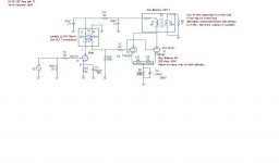
Here is a circuit you might be interested in trying, note it is not a done deal and there is plenty of room for artistic license.. Also I have not actually built this circuit, although I have simulated it in mcap with good results. (I find generally good correspondence between these simulations and the real world on other projects. I have built very similar circuits using other output tubes.) You will need to design a power supply using PSUD or similar for about 275mA at 400V for a stereo amplifier. Note that the 6AS7 will be dissipating about 20W total.. See here for information on 5842 and 6AS7 (6080 will work too!) : http://www.mif.pg.gda.pl/homepages/frank/vs.html just use search and download the appropriate data sheets. Note that output power is going to be directly dependent on the output transformer you use and at a primary of 600 ohms don't expect more than about 5 W out. I recommended the UBT-1 because it is easy to get, but in point of fact it is not the optimum choice, it will work well if you follow the guidelines in the schematic.. The primary dcr of the UBT-1 is high at 165 ohms and this implies both heat and significant losses in terms of available output power. Lundahl and James both make good alternatives to the UBT-1.
Both James and Lundahl also make suitable IT transformers, but the Lundahl is frankly better if harder to use.
It is really important that you do not omit or reduce the value of C3 as the low frequency response of the driver stage depends on the lowest possible RP out of the 5842.
In terms of filament supplies the 6AS7 cathode insulation is rated at 300V and the design is nowhere near that and the filaments may be heated by AC and I recommend 6.3VCT with the center tap being grounded.. 5842 may also be run off of the same windings and any combination may be used as long as the overall current requirements of 2.5A per 6AS7 and 0.3A per 5842 are meet. Twist the filament wiring to reduce hum induction into the other circuitry.

Kevin
Both James and Lundahl also make suitable IT transformers, but the Lundahl is frankly better if harder to use.
It is really important that you do not omit or reduce the value of C3 as the low frequency response of the driver stage depends on the lowest possible RP out of the 5842.
In terms of filament supplies the 6AS7 cathode insulation is rated at 300V and the design is nowhere near that and the filaments may be heated by AC and I recommend 6.3VCT with the center tap being grounded.. 5842 may also be run off of the same windings and any combination may be used as long as the overall current requirements of 2.5A per 6AS7 and 0.3A per 5842 are meet. Twist the filament wiring to reduce hum induction into the other circuitry.
Kevin
Attachments
Banned
Joined 2002
Replace the generator symbol with an rca jack, that is the input. Use PSUD to design your own power supply.. The program will provide all the information you need to design it.. Post the details here and I will review it to make sure it is basically correct. The program I am referring to in its latest incarnation can be found here:
http://www.duncanamps.com/psud2/
A very useful tool, and you will have the pleasure of designing it yourself. I recommend roughly a 10H choke, 47uF/630V film caps from Solen in Quebec (online) and a pair of 5AR4 in parallel for rectification - alternately a 5U4 may be used but you must allow the 6AS7's to warm up before applying B+ to prevent cathode stripping so use a switch in the center tap lead of the high voltage secondary.
- Status
- This old topic is closed. If you want to reopen this topic, contact a moderator using the "Report Post" button.
- Home
- Amplifiers
- Tubes / Valves
- 6AS7 Mono Block's