Define safe.
What bias scheme?
Considering it is only 0.5% (15.075 vs 15.000) over recommended operating condition plate dissipation I would think it would be safe.
There is a recommended op of 325V at 40mA.
Is the 335V actually from anode to cathode or is it Va with respect to ground?
What bias scheme?
Considering it is only 0.5% (15.075 vs 15.000) over recommended operating condition plate dissipation I would think it would be safe.
There is a recommended op of 325V at 40mA.
Is the 335V actually from anode to cathode or is it Va with respect to ground?
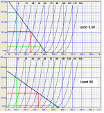
"I'm trying to run Vak 335V, 45mA for Kenrad bi-plate 6B4G. Is it safe for those tubes ?"
That totally depends on how you define "safe." The tubes at that operating point will not burst into flames, however, the recommended Max plate voltage is 250V so the tubes will not last as long as they would at the recommended operating point. I have used 275V in PP and have a Thordarson amp with a pair of 6B4Gs operating at 300V. You don't say whether you are operating in SE or PP. If you look at your load line you will see that at 335V in SE you will get a lot of 2nd harmonic distortion, while in PP you will be operating in AB2 and the distortion should cancel.
In SE I would stick close to the recommended operating point of 250V @ 60mA. Again, look at your load lines and you will see exactly why: you will be operating in a more linear part of the curves.
So far I have not assembled the amp.
I'm trying to limit the design to two stages total.
I'm testing potential driver tubes in a lab configuration with adjustable cathode resistor (fully bypassed) and Gyrator anode load. This is buffered by a FET source follower, which runs into a step attenuator (0, -20dB, -40dB) and then a Twin T filter and differential buffer to drive my sound card.
Right now I'm sorting through potential driver tubes.
I would use 1/2 6SL7 per channel CCS loaded (LND150 cascode below or just at 1 mA or IXTP01N100D cascode for 2 mA or more) RC-coupled to 1/2 6SN7 per channel wired-up as DC coupled cathode follower to the 6A3 or a FET source follower. This way one can swing more (or a lot more) than 90V p-p with considerably less distortion in comparison the 25-30% shown above (if the supply voltage is enough) and much better drive. In the end the power supply is just as important as the amplifying stages themselves for best result....
For the cathode follower you just need +/- 170V and 15K cathode resistor in order to run it at about 8 mA and get about 45V bias for the 6A3 (have a look at the classical Audio Note schematics).
I'm trying to run Vak 335V, 45mA for Kenrad bi-plate 6B4G. Is it safe for those tubes ?")
If you want go for more than 300V plate voltage then you can try with the 6C4C that is rated for 360V max. You can also run it at 16-17W plate dissipation without any problem. Actually I have also run some good Chinese 2A3's (Golden Dragon and Billington Gold) at 275V/60mA for about -51V bias. They guy who's using that amp has never got any problem. I would say that it has been running flawlessly at least for 5000 hours now!
Last edited:
In SE I would stick close to the recommended operating point of 250V @ 60mA. Again, look at your load lines and you will see exactly why: you will be operating in a more linear part of the curves.
At 275V/60mA with 3.5K load I found better results. I got less distortion and practically the same efficiency in comparison to 250V/60mA with 2.5K. If you stick to class A1 the max Pout will be just under 4W (without transformer loss). The efficiency is very similar. However I found THD to be around 3% only for 4W out. If you have a good driver like a DC coupled CF or FET follower you can easily get 5-to-6 W at the onset of clipping.
Define safe.
What bias scheme?
Considering it is only 0.5% (15.075 vs 15.000) over recommended operating condition plate dissipation I would think it would be safe.
There is a recommended op of 325V at 40mA.
Is the 335V actually from anode to cathode or is it Va with respect to ground?
Tks Gimp,
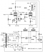
I use fixed bias, Vg ~ 60V at that ponit, 5K OPT. My schema is coming soon
That totally depends on how you define "safe." The tubes at that operating point will not burst into flames, however, the recommended Max plate voltage is 250V so the tubes will not last as long as they would at the recommended operating point. I have used 275V in PP and have a Thordarson amp with a pair of 6B4Gs operating at 300V.
I mean " safe" is long acting without problem.
Remember that data we used read is for single plate tube. Bi-plate tube have much more power. 2A3/ 6B4G seems to get twin plates of 45 tube inside.
You don't say whether you are operating in SE or PP. If you look at your load line you will see that at 335V in SE you will get a lot of 2nd harmonic distortion, while in PP you will be operating in AB2 and the distortion should cancel.
In SE I would stick close to the recommended operating point of 250V @ 60mA. Again, look at your load lines and you will see exactly why: you will be operating in a more linear part of the curves.
I build this pair of OPT for single end: 5K/ 8 ohms, Fe 32mm x 46mm. I intend use them for small tubes, eg 4P1L or 45. So the airgap is just 0.1mm and fixed by glue
, I think they cannot run over 40-42mA at idle. See 335V, 40-42mA in loading of 5K still have linearity much At 250V, 60mA of 2A3 in my friend's amp, sound is a bit slow and dark. And I don't like it.
Gimp, What is your amp like ?
Last edited:
tcqanh,
I have not built my amp yet. I am working on a coil winder to make a set of inter-stage transformers to use in it.
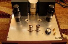
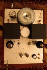
I finished my power amp 6B4G SE from modifying 4033L ampli. I use 6S45P-EB for driver. AC hum is now a bit high due to AC heater, 10-11mVac. My plan is building of separate heater power transformer and 4P1L for driver tube.
IT is my favorite.
Hi Steven
I'm on the same quest. Looking forward to seeing your results with the IT winding. Good luck!
Here's my take on the 6C4C amp:
http://www.bartola.co.uk/valves/2013/05/11/4p1l-6c6c-se-amplifier-design/
Cheers,
Ale
I'm on the same quest. Looking forward to seeing your results with the IT winding. Good luck!
Here's my take on the 6C4C amp:
http://www.bartola.co.uk/valves/2013/05/11/4p1l-6c6c-se-amplifier-design/
Cheers,
Ale
Have you tried high Gm, high gain tubes (6S45p, D3a, 7788, 6J52p...) for driver to 6B4G ? Schema become more simple, easy to build and very cheap. Sound is quite good.
I've been looking for a better driver than the 6N7 and am thinking about a 26 or maybe a 46 in triode mode.
Another option is the 3A5 with both sections wired in parallel.
If one gets 3.2 W out, that corresponds to roughly 5V driving an 8 ohm speaker.
A 5K (worst case) transformer gives a 25:1 ratio, so one needs a minimum of 125Vrms at the plate of the output tube.
Given the gain of a 2A3/6A3/6B4G at 4.2 this sets the grid requirement at 29.76Vrms.
To drive this with 2Vrms in requires a gain of 14.9 and the only tube that comes close to this requirement is the 3A5 with a Mu of 15.
Given a 3.5K :8 transformer this translates to a required Mu of 12.45, and this all presumes that the actual gain of the amp is the product of datasheet Mu of the tubes. Gain will actually be less.
So even the 3A5 is marginal.
Another option is to go with two low Mu gain and driver stages.
Even the 4P1L in triode mode only has a Mu of 8, so it would still need another stage to meet the 2Vrms input requirement.
4p1l is brilliant albeit its low Mu.
Not low gain if you use it as a pentode !
I just changed my 300B amp to 4P1L driver ( 30ma ) and it's the best I've ever had .
It would be fab as a 2A3 / 6C4C driver .
Calculate slew rate requirements before proceeding, using 20KHz bw.
For the output tube we have:
Cga = 16.5pf
Mu = 4.2
Cmiller = 16.5*4.2 = 69.3
Cgk =7.5pf
Cstray=10pf
Ctotal ~= 82pF
Sr=2*PI*F*Vpk = 2 * 3.1415*20KHz*45 = 5.654V/us
Charging current requirement is thus 82pF*324V/us = 0.464mA
Using a rule of 5 this implies a need for 2.5mA minimum Ia for a tube to drive the capacitance with low distortion. This supports my suspicion that the 6SL7 may well be slew rate limited unless it is used with parallel sections and possibly higher than specified bias current.
Gimp: I found the above very informative, but I'm wondering where you got 324V/us for charging current requirement?
82*5.654=463 which I imagine ends up as .464ma after some decimal sliding. Is the 324V/us correct or a typo?
If it's correct, where does 324V/us come from?
Thanks
- Status
- This old topic is closed. If you want to reopen this topic, contact a moderator using the "Report Post" button.
- Home
- Amplifiers
- Tubes / Valves
- 6A3 / 6B4G Design