what temperature are the heatsinks when dissipating 360W?
What is Tc of the mosFETs when dissipating 90W each?
What is the maximum power that a(n overheated) mosFET can deliver?
The dissipated power is distributed over 6 Fet's, each dissipating 60Watts. When using a .5 DegC/Watt (and you should be using .3 DegC/Watt or better) this would run at +30 DegC, on a hot summers day (let’s say 30 DegC room temp) it will run at 60 DegC[environment], like most other class A amps a bit warm but doable.
Junction to case of the IRF240 is .83 DegC, this will make the junction temperature about (60[Watt]*.83)+60[DegC environment] = 109.8 DegC[total] not a big problem (especially considering that a .3 DegC/Watt or better heat sink should be used).
The normalized power dissipation factor, for a case temperature of 75 DegC, is .6 and that makes that the Fet (at 15 DegC extra over the above shown worst case) still is capable of dissipating 120Watt*.6 = 72Watts, again no problem.
The 'AAVID THERMALLOY D180-20' heat sink could be your friend
")
Last edited:
First of all, let me add the original (1982/83 or there about) schema (do not try to build this, it is rubbish
Looks VERY familiar (below) Diodes 3/4 are there for biasing. Stealth was 1983 as well ,wonder who stole who's idea ?? It does work .. The full amp was 200/400/800W with 4 of the below "modules" in parallel. It sounded "nice" but I can easily match it with class AB's.
OS
Attachments
Looks VERY familiar (below) Diodes 3/4 are there for biasing. Stealth was 1983 as well ,wonder who stole who's idea ?? It does work .. The full amp was 200/400/800W with 4 of the below "modules" in parallel. It sounded "nice" but I can easily match it with class AB's.
OS
Yes very alike, there is one (there are more
) difference the genesis will not go rail to rail and the performance at 20Volt of the one I'm talking about is way better.In my next post I will show the 10/20/30/40Volt performance graphs (THD).
Makes you wonder, same age (around 1983...) but I am (almost) sure they did not (as I did not) publish that.
P.s. I'm sure that one is running class AB at +/- 75Volt class A will not be possible with these devices.
Last edited:
I must have misread the pic you posted.The dissipated power is distributed over 6 Fet's, each dissipating 60Watts. When using a .5 DegC/Watt (and you should be using .3 DegC/Watt or better) this would run at +30 DegC, on a hot summers day (let’s say 30 DegC room temp) it will run at 60 DegC[environment], like most other class A amps a bit warm but doable.
Junction to case of the IRF240 is .83 DegC, this will make the junction temperature about (60[Watt]*.83)+60[DegC environment] = 109.8 DegC[total] not a big problem (especially considering that a .3 DegC/Watt or better heat sink should be used).
The normalized power dissipation factor, for a case temperature of 75 DegC, is .6 and that makes that the Fet (at 15 DegC extra over the above shown worst case) still is capable of dissipating 120Watt*.6 = 72Watts, again no problem.
The 'AAVID THERMALLOY D180-20' heat sink could be your friend
It looked like 4mosFETs on the one channel.
Now back to device temperature.
Can you measure the heatsink temperature at the interface with the device/s?
Can you measure the device Tc?
I think your temperature calculations do not model your amplifier.
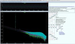
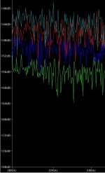
The picture shows the 10, 20, 30 and 40Volt THD graphs for a 8Ohm load
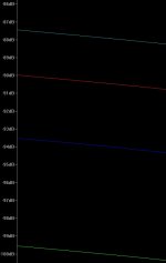
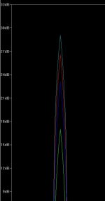
Green 10Volt 117dB to (+/-)170dB @ 20Khz
Blue 20Volt 117db to (+/-)170dB @ 20Khz
Red 30Volt 117dB to (+/-)167dB @ 20Khz
Azure 40Volt 117dB to (+/-)168dB @ 20Khz
Green 10Volt 117dB to (+/-)170dB @ 20Khz
Blue 20Volt 117db to (+/-)170dB @ 20Khz
Red 30Volt 117dB to (+/-)167dB @ 20Khz
Azure 40Volt 117dB to (+/-)168dB @ 20Khz
Attachments
In addition to the graphics, enlargements of the end points.
Attachments
-
 New 100Watt ClassA @ 1 Khz into 8Ohm 10,20,30 and 40Volt THD graph left side.JPG30 KB · Views: 385
 -
 New 100Watt ClassA @ 1 Khz into 8Ohm 10,20,30 and 40Volt THD graph top side.JPG26.5 KB · Views: 357
 -
 New 100Watt ClassA @ 1 Khz into 8Ohm 10,20,30 and 40Volt THD graph right side.JPG98 KB · Views: 351
I must have misread the pic you posted.
It looked like 4mosFETs on the one channel.
Now back to device temperature.
Can you measure the heatsink temperature at the interface with the device/s?
Can you measure the device Tc?
I think your temperature calculations do not model your amplifier.
That is why I took a .5 DegC/Watt heat sink (for the worst case example), the actual heat sink should be .3 DegC/Watt (or better, maybe add a fan). The datasheet says that the power factor is taken with respect to the case. Using good mounting practices may add .2[optimum] to .3[worst case] DegC/Watt, and that is easily handled on a .3 DegC/Watt heat sink.
http://www.eet-china.com/ARTICLES/2003JUN/PDF/2003JUN30_ICP_AN.PDF?SOURCES=DOWNLOAD
http://www.ixyspower.com/images/tec... Mounting, Soldering and Cooling/IXAN0029.pdf
Last edited:
Rth s-a (heatsink to ambient)
Rth c-s (thermal insulator/conductor)
Rth j-c (transistor to case)
Doing both of these will bring your model closer to your 3pair:
De-rate for deltaT s-a being less than ~70Cdegrees
Allow for deltaT c-s
I see 4 heatsinks, two have 1pair mounted, the other two do not seem to have any FETs mounted on them. What is Rth s-a of each of those 4 heatsinks @ deltaT s-a=70Cdegrees?
Rth s-a (heatsink to ambient)
Rth c-s (thermal insulator/conductor)
Rth j-c (transistor to case)
Doing both of these will bring your model closer to your 3pair:
De-rate for deltaT s-a being less than ~70Cdegrees
Allow for deltaT c-s
I see 4 heatsinks, two have 1pair mounted, the other two do not seem to have any FETs mounted on them. What is Rth s-a of each of those 4 heatsinks @ deltaT s-a=70Cdegrees?
AndrewT, the pictured amplifier is the one that was build around 1982, it is the one that was used as the basis for designing the current one, that pictured one has 2 Fet's and ran class AB, the current one has 6 Fet's and runs class A.
The current one only exists in the simulator, and as stated in the first message, this is the first time ever that I am using a simulator (LTspice) and I need help. Are my settings correct? The performance figures of the current version are way cool, maybe to cool? The 3rd harmonic of 10KHz at -90dB is better than most (to say the least). The THD figures in my previous messages are very good (again better than most) is that reliable?
There are a lot of questions to be answered and maybe this forum will help me, yes I need help.
Regards,
Frans.
P.s. The new amplifier will need (at the least) 6 heat sinks of .3 DegC/Watt.
Mr de Witt
Sorry, where are we going with this thread? Are we going to share something or are we just showing off some graphs. Obviously this thing has been working for the past 27 years, you do not need any comments and you are ecstatic about it, so what exactly is the point of this thread.
Nico
Sorry, where are we going with this thread? Are we going to share something or are we just showing off some graphs. Obviously this thing has been working for the past 27 years, you do not need any comments and you are ecstatic about it, so what exactly is the point of this thread.
Nico
Mr de Witt
Sorry, where are we going with this thread? Are we going to share something or are we just showing off some graphs. Obviously this thing has been working for the past 27 years, you do not need any comments and you are ecstatic about it, so what exactly is the point of this thread.
Nico
Nico, where is this going? This is not about the amplifier that was build 30 years ago, this is about an amplifier that I designed in the past month.
This is also about me not trusting the/my numbers, and before releasing the schematics and other design considerations I want to know if the numbers, the settings used to run LTspice, are viable.
As stated before this is all new to me (using a simulator) and I need some help/guidance.
Regards,
Frans.
P.s. I know people want to see the schematics, but first I need to know that I am not publishing a big mistake, what can I do, other than ask? And no, I am not ecstatic about anything, I am amazed about the numbers coming out of LTspice. And yes if these are true, then I will/may be/go ecstatic, but first let me get my numbers correct.
Last edited:
I am beginning to understand.
You are designing a new ClassA amplifier biased to 4A from +-45Vdc using 3pair of VmosFETs on a 0.05C/W heatsink.
This will be ~120W of ClassA into 4r0.
Re-check your thermal modeling. I get Tc~78degC.
I think you are right, maybe I should consider something other than TO247 and possibly I need to use 8 Fet's. Using 8 Fet's would bring Tc down to about 60DegC/Watt, so a metal can Fet may be needed. I will check it out.
Hi FdW,
you may want to open the controllcenter and deactivate all compression options on the compression-tab. this will lower the noise floor significantly. Check it every time you run LTC as this setting does not seem to be saved.
You may also want to use a window function for the FFT. I usually use the blackman window. this might improve the graph in post#25.
regards
PS:
somewhere I also read the recommendation of using stepsizes that do not divide the cycle period of the signal into an integer number of sections
Last edited:
For 360W dissipation, try : 6 pairs of IRFP and 6 of the D180-20.
Which is rather unwise in dollar terms, considering the cost of the heatsink compared to the one of the MOSFET.
Jacco, that is what I am doing at this moment, and it look promising. I would like to run with less devices, and this would seem possible with the IXTQ36N30P and IXTQ36P15P fet's from IXYS Corporation: IXYS Power, but there are no models for the P-channel devices. These devices are in a TO-3P case with junction to case thermal resistance below .5 DegC/Watt.
250W To3 have Tj max = 200degC.
That's why Krell use mj15003/4,
2pair in the KSA50 and 4pair in the KSA100.
Your much lower power FETs for 128W cannot survive long as 3pair.
I am going to try 6 pairs of 240/9240 (see post 37).
Hi FdW,
you may want to open the controllcenter and deactivate all compression options on the compression-tab. this will lower the noise floor significantly. Check it every time you run LTC as this setting does not seem to be saved.
You may also want to use a window function for the FFT. I usually use the blackman window. this might improve the graph in post#25.
regards
PS:
somewhere I also read the recommendation of using stepsizes that do not divide the cycle period of the signal into an integer number of sections
Thanks, I did find this thread http://www.diyaudio.com/forums/tubes-valves/105496-how-make-sense-ltspice-fft-analysis.html and will read it completely. You may see my graphs improve
Hi FdW,
Unless you want to takle this all by yourself, it is fine and we wait on your results, but many of us use simulators. That is one aspect of the equation. Simulators are just that simulators, it asumes perfect conditions, pure capacitors and resistors, things are perfectly matched. In other words the perfect world.
Keep this in mind before getting to extatic about the numbers presented in the FFT.
Have fun I am keen to see what comes out of this.
Nico
- Status
- This old topic is closed. If you want to reopen this topic, contact a moderator using the "Report Post" button.
- Home
- Amplifiers
- Solid State
- 63watt class A into 8Ohm, 110watt semi-class A into 8Ohm, @ 20Khz 3rd harmonic -90dB