OS, you make a compelling case. I'll give it a shot with the old transformer. I can always swap it out if it doesn't cut the mustard. Great idea about using the other secondary too. Thanks!
It will "cut the mustard" - as well as the original amp , at least. Might sound
far clearer ( 30 years of semi improvements).
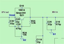
(below) is what you can do for the secondaries -
a zener- free shunt regulator/cap multiplier hooked to the "R" pads of the "Badger" CRC.
Use reverse wiring (MJE 350 + diode reversed) for the negative rail .
67V with < 2mv ripple for the LTP/VAS of the badger.
(simulated 86V unreg. secondary rails).
Your high current supply would be 60V for the output stage.
Besides the heat of the EI trafo , it is in a steel case (lower radiated field). You
might be quieter than a modern toroid build with greater PSSR (second supply).
OS
Attachments
use the standard formulae.Has anyone ever made a chart that spells out the ac output of a transformer and what rail voltage it produces and aligned that with amplifier output into 4 or 8 ohm and then the needed VA of that combination. The chart in Bob Cordell's book on pages 10 and 11 would be a great start IMHO.
P = I²R = IV = V²/R
or use Bensen's spreadsheet, or the many other guides/calculators on the Forum.
I have a rescued Yamaha M4 power transformer that has three secondaries: 62, 45, and 15 volts. The Yamaha circuit shows that the 62 volt secondaries were rectified to +/-80 volts. Is there a good amp design out there that I can cobble together so I can reuse this transformer? I've looked, and it seems that voltage is a bit high for most designs, and way too high for class A (my preference). A good class AB design would be nice. 50-100 wpc or so . . .
Thanks!

the 45-0-45 volt winding is actually used to power the output stage,
the 62-0-62 volt winding is used to power the front-end stage and is low power..
the reason the front-end used +-80 rails is because the front end is voltage regulated..
this is a common practice with japanese amps of the era...
so a honey badger is good to use with this traffo...
you can confirm what i say by measuring dc resistance of the windings and then posting them here...
The Yamaha would have likely been an AB amplifier. They aren't known to have overly robust power supplies but if you build an amplifier around the same power range at 8 ohms it should work out. If the finished product makes it into a chassis, it might be a good idea to leave some space to upgrade the transformer later if you find it's not up to the task.
it is an AB indeed...
Has anyone ever made a chart that spells out the ac output of a transformer and what rail voltage it produces and aligned that with amplifier output into 4 or 8 ohm and then the needed VA of that combination. The chart in Bob Cordell's book on pages 10 and 11 would be a great start IMHO.
yes, a look at the specs of this amp, gives you the power ratings...Yamaha M-4 Manual - Stereo Power Amplifier - HiFi Engine
you can confirm what i say by measuring dc resistance of the windings and then posting them here...
engineering guess..
the 45-0-45 volt winding will have dc resistance around 1 ohms more or less
the 62-0-62 volt winding will have dc resistance of around 10 ohms more or less...
the transformer itself will have no idea what type output stage it is used on....")
the high voltage rails in this case will have low power,
highly doubtful if it can power an output stage....
please see the yamaha M4 service data for more info...Yamaha M-4 Manual - Stereo Power Amplifier - HiFi Engine
please click on the service manual link...
the high voltage rails in this case will have low power,
highly doubtful if it can power an output stage....
please see the yamaha M4 service data for more info...Yamaha M-4 Manual - Stereo Power Amplifier - HiFi Engine
please click on the service manual link...
engineering guess..
the 45-0-45 volt winding will have dc resistance around 1 ohms more or less
the 62-0-62 volt winding will have dc resistance of around 10 ohms more or less...
62-0-62 winding is 4.8 ohms.
45-0-45 winding is 0.7 ohms.
I'll continue looking for a class AB (MOS)FET design that handles 63 volt rails . . .
Last edited:
Look here.
http://www.diyaudio.com/forums/soli...erformance-yet-rather-simple-hybrid-more.html
Look at the Fetsumo version. The Tubsumo version need +-70V but the FET version will work well with +-63V.
Of course the P101 mentioned earlier will work fine with those rails too.
http://www.diyaudio.com/forums/soli...erformance-yet-rather-simple-hybrid-more.html
Look at the Fetsumo version. The Tubsumo version need +-70V but the FET version will work well with +-63V.
Of course the P101 mentioned earlier will work fine with those rails too.
62-0-62 winding is 4.8 ohms.
45-0-45 winding is 0.7 ohms.
I'll continue looking for a class AB (MOS)FET design that handles 63 volt rails . . .
spot on i would say....
Look here.
http://www.diyaudio.com/forums/soli...erformance-yet-rather-simple-hybrid-more.html
Look at the Fetsumo version. The Tubsumo version need +-70V but the FET version will work well with +-63V.
Of course the P101 mentioned earlier will work fine with those rails too.
That FetSuMo looks fantastic! I think you've found my next amp. Thanks!

- Status
- This old topic is closed. If you want to reopen this topic, contact a moderator using the "Report Post" button.
- Home
- Amplifiers
- Solid State
- 62-0-62 volt power transformer: options?