Well, you can tell I have only been following this thread with a spare minute or two that I get here and there. Looking at the schematic, what you say is obvious.
I did however notice that you kept bringing up adding "Schade" and or cathode feedback. Depending on how much feedback applied, you may want/need something special in the stage before the driver.
Anyway, I'll shut up now. I've just been pretty excited about that circuit since I performed that test. I haven't had a chance to work that into anything yet.
Edit: I'd start a new thread. I find that when I tack a new topic onto an existing thread I get very little response.
May be I missed it earlier, but what's the primary impedance of the OPT?
Calculates to less than 400 Ohms. Transformer ratio will be a very favorable about 8:1 with a 6 Ohm speaker load.
OK, good people, I'm forcing myself to make time for an update.
Still have not had time for a complete analysis and detailed schematic, not even for the power supply which for me is a "been there, done that" thing. Clients have been keeping me busy plus the complication of the Harvey effects.
But I did zero on what I believe is the most challenging job, that of driving the output traditionally called V1 or the "upper" tube, the one with the load on its cathode.
The plate load resistor of its driver (let's call it V1D) is sensibly returned to the plate of the other output tube (the one with the load winding on its plate), let's call it V2 (and its driver V2D). This provides a higher supply voltage when V1D is swinging positive and V1's cathode is also swinging positive, in our case by 200V.
A bit of review:
A B+ of 260V was chosen together with a swing of 200 in order to get the power wanted while keeping the cathode swing to within cathode-heater limits and not forcing the need for a floating heater supply. We are taking advantage of the sweep tube's very high current capacity so no need for higher voltage.
The reason for 260 and 200 is of course the knee of the 6DQ5's plate characteristics. The remaining 60 volts keeps things on the knee or slightly to the right.
So when V1 cathode is swinging positive so is V2's plate and the ability of V1D to drive V1's grid is preserved. If we only had to drive in the positive direction, we'd be done and life is good.
It's when we need to drive V1 to full cutoff that things get hairy. V2's plate voltage at that point has dropped to 60, while V1D must be able to pull down V1's grid to -50. We are AC coupled so actual DC voltages are not the issue, but the ability to swing and maintain while the relative voltages are changing is an issue.
V1D's plate voltage must drop by 50V in the presence of V1's cathode voltage actually swinging below ground by 200V. So V1D can't simply stop swinging low because then V1 would drive itself into conduction since V2 is actively being driven low hence inducing the negative V1 cathode voltage.
The solution seems to be to return the cathodes of V1D and V2D to a suitable negative voltage. In order to again not require a floating heater supply, this B- has to be within -200V, preferably less.
Recall that the 6VJ8 (two of them) was selected for both phase inverter (LTP with CCS, the triodes) and driver (V1D and V2D). The operating plate current of the drivers, the pentode sections, is around 8mA which means the G2 supply is going to be less than 100V which favorably moves the plate knee to the left. Still, I'm concerned about leaving less than 60V across V1D since the G2 current will go up significantly, and the intention was to operate V1D/V2D as LTP to linearize the drive in the presence of very disparate plate swings for each. A sharply rising G2 current will introduce errors in the LTP operation.
Current status is reviewing the choice of the 6JV8 (I really like their triode sections) in veiw of their relatively low plate voltage max limit and 4W PD. Maybe a 6DT8 for the LTP phase inverter and a pair of 12HL7 for the drivers is a better choice. It's possible then that we can use a negative rail of 150, and by a necessarily low G2 level move the plate knee way to the left, perhaps as low as 25V and get plenty of margin this way. The 12HL7's PD is much higher at 10W, though with the plate current idling at 8mA and swinging +/-4mA from there, dissipation remains closer to 3W.
OK, let me not make promises I clearly can't guarantee anymore other than I'll do my best to complete at least the schematic for the power supply and write its analysis, and continue on the amp. Eventually, I'll have to actually design the transformer. I'll publish the details so y'all can either build your own or have someone build to the specs.
As usual, any and all feedback is both solicited and welcomed, as well as any questions.
Be well,
Rene
The voltage constraints from heater to cathode V, and from driving the top tube, V1, do appear to be excessively tight. Good idea to go with a separate tube for the LTP CCS or even a SS CCS. I think this is what Mona was getting to about B- still being needed. You don't want to be caught short on voltage drive capability with a totem pole design.
The 400 Ohm loading (on each 6DQ5) may be within the tubes current capability, but this may be lowish for good quality natural sound from the tubes. Of course, the amount of N Fdbk around all this could fix that, being mainly low harmonics.
If one looks at the TV Sweep tube amplifiers around, they are typically using a higher OT primary Z. Even "abnormally" high primary Z when compared to typical "audio" tube loading, allowing for the ratio of cathode current capabilities.
For example, Pete Millett's 50 Watt monoblock is using a 4.3 K P-P OT with 6HJ5 tubes (280 mA max DC cathode, very similar to 6DQ5 at 315 ma). Comparing that with a 6L6GC, with 110 mA max DC cathode, that would correspond to a 280/110 x 4300 = 11000 Ohm Zprimary OT for the 6L6 !!
People who hear one of these "cheap" TV sweep tube amps can't understand how they could sound so good. Well, the typical OTs around (for "audio" tubes) almost force one to make an outstanding Sweep amplifier.
Following that higher level of effective primary Z would certainly bust the voltage constraints for your totem pole design without extensive re-working of the driver. (George still gets good results using a 3300 Ohm P-P OT) So I would recommend allowing room for further drive V extension for possible later mods or experiments. (B- V tracking B+ V would be easy, and multiple taps on the OT secondary to adjust loading)
Last edited:
Lots to digest, thanks.
For sure the driver pair was always envisioned as LTP with CCS and I'm perfectly happy, in fact happier, with sand CCS rather than glass CCS. They really must be LTP if differential (as opposed to the P-S use of the split load PI which only works with a single Primary and much higher B+) due to the very different plate voltage swings each sees. CCS will clean up most of the sins there, maybe all of them. A -150V is beginning to look like the ticket, with 12HL7 drivers. There is a bit of hope left for the 6JV8, I need to derive the plate curves for a G2 voltage low enough that the max plate current with near zero bias, say -1 to stay away from grid current altogether, is 12mA. I can see the 12HL7 dong this with a G2 of about 75V, just don't know yet about the 6JV8. A matter of doing the math, unless someone has access to the tube and a curve tracer") If it can be determined that the knee is less than, say, 40V at 12mA, and the G2 current has not risen by more than a couple of mA, might be able to still use the 6JV8.
If it can be determined that the knee is less than, say, 40V at 12mA, and the G2 current has not risen by more than a couple of mA, might be able to still use the 6JV8.
Taking in all the comments regarding impedance. Unless the power is going to be allowed to be a whole lot less, it surely means higher B+ and more capability from the drivers.
I'll think about it of course. My inclination is to believe that the vastly reduced turns ratio and the much reduced sensitivity to primary side leakage inductance will help a bunch.
What is the principle behind thinking that a primary Z an order or more in magnitude higher than the calculated one is better for the sound? I need an education there.
Thanks,
Rene
For sure the driver pair was always envisioned as LTP with CCS and I'm perfectly happy, in fact happier, with sand CCS rather than glass CCS. They really must be LTP if differential (as opposed to the P-S use of the split load PI which only works with a single Primary and much higher B+) due to the very different plate voltage swings each sees. CCS will clean up most of the sins there, maybe all of them. A -150V is beginning to look like the ticket, with 12HL7 drivers. There is a bit of hope left for the 6JV8, I need to derive the plate curves for a G2 voltage low enough that the max plate current with near zero bias, say -1 to stay away from grid current altogether, is 12mA. I can see the 12HL7 dong this with a G2 of about 75V, just don't know yet about the 6JV8. A matter of doing the math, unless someone has access to the tube and a curve tracer
If it can be determined that the knee is less than, say, 40V at 12mA, and the G2 current has not risen by more than a couple of mA, might be able to still use the 6JV8.Taking in all the comments regarding impedance. Unless the power is going to be allowed to be a whole lot less, it surely means higher B+ and more capability from the drivers.
I'll think about it of course. My inclination is to believe that the vastly reduced turns ratio and the much reduced sensitivity to primary side leakage inductance will help a bunch.
What is the principle behind thinking that a primary Z an order or more in magnitude higher than the calculated one is better for the sound? I need an education there.
Thanks,
Rene
People who hear one of these "cheap" TV sweep tube amps can't understand how they could sound so good. Well, the typical OTs around (for "audio" tubes) almost force one to make an outstanding Sweep amplifier.
Hundreds of thumbs up! And the mistake is more commonly in near sighted admiration of expensive tubes due to fancy written comments and articles. Many builders just accentuate on the tube and neglect so much other important things.
The Russian 6P45S (6П45С) is a herroic tube. I've been running it with 380V on G2, triode strapped for three years, as well as a few fans of it I know. Some have even reached 400V. And 42W of total dissipation. Pity these are so expensive on eBay, but here locally, they can be found for dimes at flea markets. I have around 30 of these.
The other favorite of mine is the PL36. Awesome sounding tube for potentially low price (at flea markets again).
I've been running an amplifier with 330V on G2 on this one, sturdy too as well."What is the principle behind thinking that a primary Z an order or more in magnitude higher than the calculated one is better for the sound? I need an education there."
Well, the 6L6GC datasheet has an example with a 5000 Ohm OT (P to P), so the 11000 Ohms (above post calc'd equivalent) is not quite an order of magnitude over that. I'm sure most of the OTs chosen for TV Sweep amplifiers have either been selected by best fit on the datasheet curves, or by trial and error. It's just that the OTs available (generally for "audio" tubes) allow one to choose an "effectively" high Z OT (as a result of the tube current ratio), so those higher Z load lines are not ruled out. And the OTs chosen for Sweep use are still toward the lower end Z pri OTs available, so bandwidth is still not an issue. (like less than 5000 Ohm)
There is some logic to the higher Z choice as long as screen current distortion does not get in the way. A low Z primary means more current variation to handle the signal power, which in turn means more variation of the tube gm. (from tube 3/2 power law variation) The gm variation of course leads to distortion (at least in typical class AB). So it is advantageous to tilt toward a higher Zpri OT. The higher Zpri is just operating over a smaller section of the gm curve. (similar to the 5X Rp rule for triodes) Also, the tube efficiency improves since the knee voltages become a lower % of the total V swing.
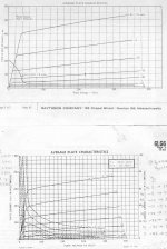
The limiting factor to raising the OT primary Z is screen current distortion. This causes the individual tube plate curves to, well, "curve", instead of just being straight lines. Going to too high a Z primary picks up distortion from the load line going through compressed together plate curves as it approaches the left (knee) side. Fortunately, many of the TV Sweep tubes were late designs with an emphasis on low screen current, so this is minimized some. (examples below, top set is 6HJ5, but Raytheon was a bit over optimistic on these! they don't look THAT flat on the curve tracer) (on the flip side, the compressed knee side curves at high current, like seen in pentodes, 6BQ5/EL84, EL86/6CW5 ... are useful for SE applications to reduce high 2nd harmonic)
So we often see the 2x (effective) increased impedance factor show up in Sweep tube designs. On the down side, however, this leads to higher B+ for any significant output power. And the relatively lowish harmonic gm distortions avoided by using a higher Zpri is nothing some additional N-Fdbk cannot take care of. (class AB cross-over dist. being the far more traumatic problem with it's higher harmonics)
So this "effective" high Zpri is no hard and fast rule, often just a happenstance convenience, I think, from using readily available OTs with Sweep tubes. The results nevertheless have been impressive in many cases, especially low global Fdbk designs. In any case, not hard to try out with a few assorted OTs off the shelf and a variable B+ bench supply.
Attachments
Last edited:
The screen current distortion (compression) that the P-P load line runs into at high amplitude (and especially with a hi effective Z OT) is not necessarily bad sounding either. Producing a softer clipping effect (when without high N-Fdbk).
Whereas the gm distortion effect (using a low Z OT) manifests throughout the full signal amplitude range. So a Hi-Zpri OT can then be helpful for low (listening level) gm distortion and soft clipping for a lower power, and low N Fdbk, amplifier. Low screen current tubes may not even be welcome in that case. Pentodes like 6BQ5 and EL36 may be popular for low power amplifiers due to their strong compression effects at peaks.
Bigger (and low screen current) Sweeps like the 6HJ5 and 6LG6 probably are big enough that clipping is not much of an issue typically (50, 75, 100 Watt output), so they can be helpful in maintaining high linearity throughout most of the operating range. A hi effective Zpri OT then working well for the lower gm distortion in a low N Fdbk design. Horses for courses.
Design trade-offs.
Last edited:
Thanks for the analysis!
OK, on the "order of magnitude" thing, is what I get for reading things on the fly. I thought you had recommended in the order of 5K for the sweep tubes under consideration. You were comparing 6L6 to 6L6. Got it now.
I will say at this point that I have so far only looked at power in coming up with the primary Z and not compressive/gm/G2 effects. Add all those to the analysis list. I do expect NFB to take care of a lot of evils. The "notch" distortion caused by primary leakage inductance, which is not correctible by NFB, should not be a factor here. And if it does wind up existing, it will be small and can be eliminated by raising the Iq. Cross over due to non linearity about the load line transfer zone is correctible via NFB, and responds to adjustments in Iq. You have already pointed out both.
Off hand, I'm probably not going to be too concerned about G2 current for the outputs as the source will be regulated. The circuit being planned is "floating" such that the G2-Cathode voltage will be maintained. The effect of G2 current on transformer primary current (instantaneous) does need to be analyzed carefully. It can be, and will be, mitigated by the use of a "large" cap from G2 to K.
All the other effects you mentioned are to be considered.
As an old controls engineer, I am not the least bit afraid of using as much NFB as possible. I am comfortable understanding all the phase shifts, etc, etc, which must be considered when applying large percentages of feedback and expect it to linearize things to a satisfactory point. Most likely, nested feedback will be used and still an overall loop included. No details, just conceptual. The servo systems I currently design to work at up to 200C all utilize very high open loop gain, with a closed loop gain of 1. If that does not teach one to learn how to make things stable over the dynamic range, I don't know what will. It's a great deal of fun.
In the end, as you well put it, "horses for courses, design trade-offs". Which is why I do not listen to "gurus" but I do listen to technical people.
Any insights on the driver questions raised so far? BTW, looking at the necessary behavior of the drivers in a differential topology makes it clear only pentodes or beam tetrodes will work best. Triodes have to be forced to work. One must have a current (transconductance) device as drivers, though an LTP with a good CCS might allow triodes to work. But in that case, one is relying totally on the LTP effect to make things work, while the use of pentodes is getting you there fundamentally and the LTP is soaking up the less than ideal tube characteristics. So much for the "triode only" guys. Each type has its place and best use.
OK, oil is up to $48/bbl so I have work to do.
Pray for those in Irma's path, it's ugly.
Rene
OH, I should have also mentioned that a high Zpri OT improves the damping factor for the speaker. Which N Fdbk can do also.
Many low N-Fdbk designs around these days, so a different set of criteria from your present design.
For a driver into the low impedance of "Schade" shunt Fdbks, some have used Mosfet followers with series resistors, after the driver. A very constant Fdbk divider ratio then. More parts though.
Without the Mosfet followers, the driver output Z, or Rp, will have some small effect on the shunt Fdbk divider ratio. Not much effect from a pentode driver, but triode drivers will cause some 2nd harmonic cancellation effect from varying Rp. (also a small up-tick in higher harmonics)
To the extent that the transformer magnetic coupling between Pri and Sec is maintained as the turns ratio increases, you are correct on the damping. At very low frequencies (where I suppose damping is most needed, not a speaker expert) the coupling will tend to be best. As frequency increases, great coupling gets more and more difficult to be achieved. In the end, turning the amplifier into a constant voltage source via NFB should work wonders for the damping. All things equal, coupling is better when the turns ratio is closer to unity. But of course, the open loop source resistance presented to the speaker is lower, all other things equal, if the turns ratio is higher. Again, trade offs, always rearing its ugly head!
In fact, I followed a thread by Heath Workman (his blog HERE) referred in this thread, using MOSFETs as buffers with the advantages you mention. Intriguing idea, won't toss it just because of additional parts. Can be used to help reduce the possibility of blocking distortion.
Would be an improvement over just the pentode drivers and may be worth it.
I am not ruling out many things at this stage and I will take another look at triode drivers in combination with a MOSFET driver but at first blush, don't see why that would be better than the pentode drivers, with or without sand buffers.
Rene
Using any of the 9-10 Watt pentodes mentioned earlier (6GF5, 12HL7) for drivers should eliminate any real need for the Mosfets. But 6JV8, maybe.
On the OT leakage L issue, we often obsess over that, but current sources (pentodes) don't even see it. Just some extra V headroom needed to overcome that. (well, the distributed C would affect that some) Ideally the output tube cathode would use a low leakage L winding, and the plate (pentode) would use a low distributed C winding.
Theoretically, the OT has a (bad) two pole freq. roll-off from the combined leak L and dist C, but many tube amplifiers appear to shunt one of those elements out of the equation sufficiently, from either a low Z source, or a high Z source. (changing the OT to a safer single pole response) They get by without any freq. compensation network for the N Fdbk (for stability) then. Of course, best to do the full workup to make sure its working. A low Z source (from local N Fdbk) probably works best, since the distributed C is encountered before the leakage L.
I think the 1st order design rule for the OT is to get the leakage L and distributed C to be resonant with an internal Z that matches the driving source paralleled with the load. So giving maximum damping of the OT resonance. Plate and cathode sources represent quite different source impedances. Local N Fdbks affect the source Z too.
I think the bootstrapping in the totem pole design gets the top and bottom tube output characteristics more or less equal. But, then again, the top tube driver is using a positive feedback bootstrap, which will affect output Z there. That definitely needs to be checked out. (Spice sim.) One might consider using the bootstrap for a V source for a floating CCS load for the driver, to eliminate effects on the source Z. Having two different output impedances for the top and bottom tubes could definitely affect the sound. I hadn't considered that before, nor seen any mention of it.
Maybe this is has caused asymmetric designs grief in the past? This needs checking into.
Last edited:
I agree, the MOSFET thing would be more to provide blocking effect resistance and to make the math a snap for the Schades.Using any of the 9-10 Watt pentodes mentioned earlier (6GF5, 12HL7) for drivers should eliminate any real need for the Mosfets. But 6JV8, maybe.
Perhaps, but my painful experiences over the years with power supplies has taught me to not ever underestimate L leakage. Also, the way I see it, both tubes are effectively plate loaded, not cathode loaded, since the drive signal is applied G1-K in both cases. You are right about distributed C, it must be taken into account, whether by reduction or deliberate incorporation or nullification or whatever. Fewer primary turns certainly helps there.On the OT leakage L issue, we often obsess over that, but current sources (pentodes) don't even see it. Just some extra V headroom needed to overcome that. (well, the distributed C would affect that some) Ideally the output tube cathode would use a low leakage L winding, and the plate (pentode) would use a low distributed C winding.
This is going to be a super fun, or super frustrating part of this project. Probably why so many fail at including a lot of correction (NFB) and then proclaiming correction to be a bad thing. This is one area where just aimless tinkering is not going to get you there. One must have a solid understanding of all the effects involved before applying counter measures, or one can easily make things worse when expecting them to get better and wind up very, very confused. Not to say that there won't be any experimentation involved, there will likely be but it will be in the area of zeroing in on values and not overall topology of the correcting networks.Theoretically, the OT has a (bad) two pole freq. roll-off from the combined leak L and dist C, but many tube amplifiers appear to shunt one of those elements out of the equation sufficiently, from either a low Z source, or a high Z source. They get by without any freq. compensation network for the N Fdbk (for stability) then. Of course, best to do the full workup to make sure its working.
Yup, covered above. Mitigating procedures. The fewer primary turns should put the remaining leakage L at a low level, together with low C, pushing things way high in frequency (I can dream!). Shaping the feedback network is part of things. Without knowing the numbers yet, I envision a network passband restricted to stay out of trouble.I think the 1st order design rule for the OT is to get the leakage L and distributed C to be resonant with an internal Z that matches the driving source. So giving maximum damping of the OT resonance. Plate and cathode sources represent quite different source impedances. Local N Fdbks affect the source Z too
Again, I think it's really inherent and both tubes are being operated identically, just a physical thing as to the order. The totem pole arrangement reminds me of early (1960s) transistor power amplifiers, where it appeared at first glance that one device was emitter loaded while the other was collector loaded, but in fact both were collector loaded.I think the bootstrapping in the totem pole design gets the top and bottom tube output impedances more or less equal.
Gotta get some RFQs out and the wife is calling lunch. Later!
Hmmmm...
The driver bootstrap arranges for the top tube to be driven in common cathode mode, like the bottom tube. So far so good. But...
The driver load resistor is affected by this positive feedback bootstrap. If the output (top) tube is having trouble pulling the load up sufficiently, then the driver load resistor is not pulling up sufficiently either. Effectively making the driver load resistor look like a higher resistance and spoiling the drive capability. Then again, the bootstrap cap still has the same voltage across it relative to the cathode, should be like a CCS with constant V across the driver load resistor. Maybe not a problem after all? The Mac design, with bootstrapped drivers (at least both are symmetric) does see a change in overall N-Fdbk from the bootstrap P-Fdbk.
If the output tube were readily keeping the output V up, then the bootstrap C would be applying a higher V to the driver load R, versus the case of having difficulty pulling the load up. To get the same required grid V for the output tube (under load) will require more of a current drop from the pentode driver tube. So gain is affected. Yeah, that should in turn affect the output Z.
Houston, we probably have problem. Get out the Spice simulator please.
Where is Mona? Probably loading a shotgun to shoot this whole thing down now.
I'm sure some fix can be found if needed. More parts somewhere. I wonder if N. Crowhurst ever wrote about this totem pole design. Or if anyone has worked on this, successfully... Broskie at TubeCad maybe? I don't recall any mention of the output Z issue before.
Last edited:
I did some looking around for totem pole designs and came across this one:
http://www.mellowacoustics.com/articles/Tim_Mellow_25w_OTL_Tube_amplifier.pdf
For which there is currently an active thread here.
What is interesting in that design is the use of a negative Fdbk bootstrap instead of a positive Fdbk bootstrap. So the top tube ends up being driven as a cathode follower, and the bottom tube is shunt "Schaded". Essentially what you get if you add shunt "Schade" to each tube in the present design. Requires more driver current for the bottom tube. Similar voltage for the top tube I think.
I think this still has asymmetry from top versus bottom output Z though. Some analysis needed yet.
Not ignoring things, just saw the posts and thanks, but out of time today.
I am convinced that we are looking at a symmetrical loading (of the outputs) situation but need to justify by analysis.
Always thanks for pushing, is how good engineers respond to challenges that make them good.
Rene
I am convinced that we are looking at a symmetrical loading (of the outputs) situation but need to justify by analysis.
Always thanks for pushing, is how good engineers respond to challenges that make them good.
Rene
Looks like either driver pentode has to adjust the drive current by the same amount for an added output load current. So I'm leaning toward equal output Z for both top and bottom now. Would be nice to confirm though.
That Tim Mellow amplifier appears to be exactly what one gets if "Schade" shunt feedback is added to the top and bottom output tubes here. It apparently has equal output Z's also. But much lower due to the local N Fdbks. Requires 2X higher driver currents I think.
OTL designed by Tim Mellow with 4 6C33C?
Last edited:
OOPs. Make that approx. Mu times more driver current with the N Fdbks. Mu being the V gain of the bottom output tube. (for the same kind of driver load R)
Those EF86 drivers in the Mellows design seem a bit wimpy for driving a CF and a "Schade" output. And certainly for a higher V Sweep tube version. That 6JV8 tube might work fine.
Those EF86 drivers in the Mellows design seem a bit wimpy for driving a CF and a "Schade" output. And certainly for a higher V Sweep tube version. That 6JV8 tube might work fine.
Hey Rene,
in general you might only need high damping at the driver resonance which might not be at the very low end. However it really depends on the driver! There is no general rule. I have recently uploaded one example in another discussion. Look into my recent posts....
I only see feedback as a tool to get low distortion. I mean all forms of distortion I can measure from the entire system. As this is not always the case, I only use feedback when it works. High damping factor can induce more distortion into the driver that a low damping factor becasue (to cut a long story short) the driver has already "the right amount of self damping". Forget dummy loads and catalogue figures they will never tell you how good the amp is....
So my suggestion is don't use Zout as a design parameter for the amp but rather linearity.
Smoking-Amp and 45, thanks for the posts.
This has turned out and continues to be a very, very interesting project which clearly is exercising us collectively. Hooray!
45, I'm with you regarding Zout though mostly out of ignorance on speakers. I am generally aware or speaker driver resonances, having seen a lot of curves, and can clearly hear some speaker systems "booming" at what has to be some sort of resonance. In controls, we use a low source impedance to control the movement of the driven widget since it acts as both a driver and a brake. I can only assume that generally this is what we want in an audio amp viz a viz the speaker being driven.
But in the end, I have to assume that the most precisely damped speaker will not sound good if the linearity of the amp is not there.
Smoking Amp, I can see that this is as challenging to you to noodle out as it is to me. No standard and/or shoot from the hip will do here.
I am still hoping the 6JV8 will do, really just because its triode section is so cool but, really, a 6DT8 will work fine together with a pair of 12HL7s if that is what it takes. Or the MOSFET buffer idea, that is not off the table. I am actually a bit more concerned about my heater power budget than the number of tubes or losing the 6JV8s, as I had already picked out a 12V supply. The next size up in current is quite a jump. We'll see.
I sure wish I had the time right now to really dig deep and get the design analysis done. Maybe in a couple of weeks when the wife and daughters go out of town for a few days.
Meantime, oil is still up and got about a dozen paying prokects
I think that I'll formalize the dissection I have been doing on the drivers to the outputs next, I think it will help us all to determine if we indeed have symmetry on the output stage and that both are in fact being driven as common cathodes.
I'm already looking for a source of EI-125 (M6, 29Ga grain oriented good stuff), bobbins and end bells. The rough transformer design is done, pending final details of course. I have been also looking into "glass" C cores. I have a simple manual winding machine I use for the small stuff I make for the clients and I would hate to do any production work on it but should be OK for a couple of units.
It's putting the cart before the horse but I might go ahead and publish the schematic in my mind right now, even knowing that it is subject to changes as the formal analysis progresses.
Trying to get a hold of my brother who lives in Miami. Hope if any of y'all have relatives in So FL that they have taken proper measures, Irma is big and she's mad.
Rene
- Status
- This old topic is closed. If you want to reopen this topic, contact a moderator using the "Report Post" button.
- Home
- Amplifiers
- Tubes / Valves
- 60W With Sweep Tubes, Different Topology