Well, things are coming along. The power supply checked out great, no problems. The lightbulb tester was a comfort - I've never used one before.
I was about to plug in and test my first amp module, when I found there was a short - between the + and - power supply! A quick look and I realized my transistor pads were not insulating. Word of warning - BER131-ND heatpads, from digikey, are not made to insulate, unfortunately. They make others that are electrically insulating, they're a little expensive though.
I eventually found mica pads that are appropriate for TO247 cases, 4672-ND, if anyone is interested. Time to put in an order, I guess...
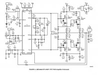
About your power dissipation question, the 35.1W maximum is for the system. The equation takes into account the de-rating of the output devices based on the heat sink temperature rise. So when all this is accounted for each device can safely handle 35W of power dissipation. Now if the heat sink is made larger (lower thermal resistance) or a fan is used, or more output devices are used, then the numbers change. So yes, your understanding is correct that if you want to drive lower output loads or have a higher supply voltage resulting in higher maximum power dissipation you would need to change something in the system to handle it. But this is maximum with sine waves so more of a worst case number. Of course, when you take into account the phase difference with inductive loads then your numbers can get pretty high. Keep posting your progress as I am interested in your result. I was going to build a design with 3 or even 4 output devices per side but will not get to it anytime soon.
-Troy H.
-Troy H.
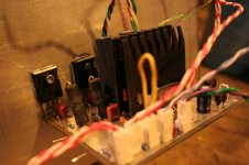
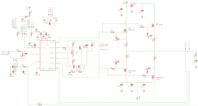
So everything has powered on fine. I found the relay and muting circuit were not switching on, and realized I hadn't connected them to ground - I construed the schematic in AN1849 as having three different grounds...
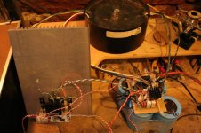
The amp module seems to be fine, almost. Almost let out some magic smoke though - when I connect a load (11ohms), but no signal, I get 1.3MHz oscillations, looked like a triangle wave (about 10Vpp). I had this going just long enough to see it on the scope, then the magic smoke started to escape, and I switched everything off. I gave it a couple of seconds to let the voltage drop, then started feeling for what was hot - I couldn't find anything! It must have been the 10ohm, 3W snubber resistor on the output (Rsn). The transistors were cold. Load resistors were getting hot though.
Also, with no load, I can't get a signal to appear on the output (no load). I applied 1kHz square wave, and got some sort of 1kHz spikes as some sort of low voltage noise.
I'm not sure what I'm doing wrong - why is it oscillating so bad with a load, but won't pass a signal? Hmmm....
PS - I'm not sure my bias voltage is working properly either - I only get a small range of voltage from the pot - about 3.45v to 3.65. I suspect something there. How do you calculate the amount of bias current per device?
Attachments
cuibono said:PS - I'm not sure my bias voltage is working properly either - I only get a small range of voltage from the pot - about 3.45v to 3.65. I suspect something there. How do you calculate the amount of bias current per device?
Fig 7 from the IRFP240 data sheet (attached below) is the "Transfer Characteristics": is that what I need to translate bias voltage to bias current? Also, the LME app note says the bias voltage measurement is 'gate to gate' - do I need to half the measurement to use it in the graph?
I guess the simple way would be to measure the voltage across the source resistor - but why isn't my bias voltage going high enough? Hmmm...
Thanks much
Attachments
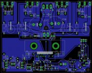
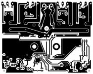
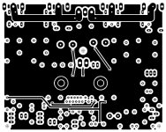
cuibono said:Here is the layout including the top layer:
cuibono - are you willing to share brd file ?
in fact - all I need is LME footprint ....... so - if you are willing to share any of that , I'll do rest in Eagle , with less trouble
")
I have intention to make smaller power amp , but with 3 pairs of output mosfets
TIA
Zen Mod -
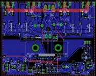
Of course, thanks for reminding me. I'll attach the part file. If you look, you'll see I've included the footprint for a heatsink. You can find the part number in AN1850, or of course, edit the heatsink out.
The library is 'zipped'. Please let me know if the library doesn't work for you.
Enjoy
Of course, thanks for reminding me. I'll attach the part file. If you look, you'll see I've included the footprint for a heatsink. You can find the part number in AN1850, or of course, edit the heatsink out.
The library is 'zipped'. Please let me know if the library doesn't work for you.
Enjoy
Attachments
- Status
- This old topic is closed. If you want to reopen this topic, contact a moderator using the "Report Post" button.
- Home
- Amplifiers
- Chip Amps
- 6 channel LME49830 power amp