Thanks Andrew ")
Cheers Einric and go for it, If you have any questions just PM me.
I will post a few more photo's in the next few days for inspiration and may even have the beast running by the end of the week.
Can you give any subjective impressions/comparisons on how hours sounds, I have never heard any of the LM series.
Maybe I should have started with one kit and built my way up... lol
Dean
My LM4780 & Speakers
I tried the LM without "Snubber" and Big uF first.
I liked it very much. It sounds better than my 120W Class H.
I have a feeling that in Stereo mode the LM4780 lacks drive for low sensitivity speakers that have dual 5.25", single 8" or larger drivers.
When I built the TriTrix MTM TL kit from Parts Express they lacked bass without some sort of boost when run by the LM4780 in stereo.
Once I hooked it up to my Class H the bass came back.
I then went through and added the "Snubber" & 10000uF.
After that I have not been driving large speakers just my home made 4" 2-Way bookshelves.
They are approx. 86db sensitivity and this amp in stereo mode will drive them off my laptop until they nearly explode.
Under more reasonable drive condition the amp sounds more wonderful than I could ever imagine.
I can't wait until I parallel the chips and re test the drive capability with my TriTrix.
I am driving my single chip in stereo with dual 24v secondaries @ 240va.
I figured that when in stereo @ 8ohm or 4ohm in parallel mode.
I am running the amp on a line conditioner so I don't really have to worry about line level fluctuation.
Attachments
Last edited:
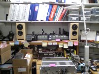
Nice work Einric, I must say I have a bit a bit of workbench jealousy after looking at your photo. It looks like a bit of geek heaven going on there.
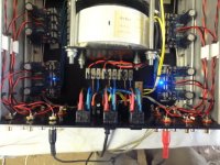
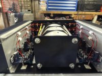
After some advice from Andrew I decided to go for the parallel config, hoping that the amp could be used in as many situations as possible (tolerant of load and flexible with connections).
The transformer stack was the only way I could fit 3x400VA Antek units in a standard size chassis, but she is a heavy bugger.
The top, bottom and front plates are 5mm thick hand cut alloy. I did these the hard way with a 1mm blade on a 4" grinder. I don't recommend this at all. An alloy blade on a 10" drop saw is much easier but I didn't find this until cutting the 3mm back plate. Even with the 5mm alloy it just glides through like butter.
I also had allot of trouble tapping m3 holes in this alloy. Its 4000 series and very easy to cross thread the holes with fine threads found on m3 bolts.
M4 is much easier and would really be my minimum in the future.
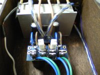
The LM4780 wont fit anything larger than an m3 in the cutout on the chip die, so as you can see I used a clamping plate and m4 bolts. The other advantage here is that hopefully the bar acts as a further heat spreader for the chip. Apparently the 4780 package cant dissipate enough heat when run full power (it probably wont be used that hard anyway), so this might help.
Getting the last terminal strips today which should complete the wiring.
Dean
After some advice from Andrew I decided to go for the parallel config, hoping that the amp could be used in as many situations as possible (tolerant of load and flexible with connections).
The transformer stack was the only way I could fit 3x400VA Antek units in a standard size chassis, but she is a heavy bugger.
The top, bottom and front plates are 5mm thick hand cut alloy. I did these the hard way with a 1mm blade on a 4" grinder. I don't recommend this at all. An alloy blade on a 10" drop saw is much easier but I didn't find this until cutting the 3mm back plate. Even with the 5mm alloy it just glides through like butter.
I also had allot of trouble tapping m3 holes in this alloy. Its 4000 series and very easy to cross thread the holes with fine threads found on m3 bolts.
M4 is much easier and would really be my minimum in the future.
The LM4780 wont fit anything larger than an m3 in the cutout on the chip die, so as you can see I used a clamping plate and m4 bolts. The other advantage here is that hopefully the bar acts as a further heat spreader for the chip. Apparently the 4780 package cant dissipate enough heat when run full power (it probably wont be used that hard anyway), so this might help.
Getting the last terminal strips today which should complete the wiring.
Dean
When I complete my 7 or 8 channel version of the Parallel LM4780 I was looking at mounting the 1500uf's on the bottom of the pcb for easier mounting to the heatsink.
I used M4-40 just fine on my chip in the picture, i used the washer head ones from a computer fastener kit.
I was also looking to use Computer Memory heatsinks on the print side of the LM4780 to help facilitate even more cooling.
I could then attach a spreader or just use it as the clamp to hold the LM's in place.
I would recommend using a little thermal paste on the topside of your chips to help maximize dissipation (everything helps).
I too am using Antek transformers (AS-2224), since I am on 60hz power the manufacturer states the transformers will provide approximately 20% more power (bonus for me).
I really like the way you stacked your transformers.
I will probably look at doing something similar with three 400VA's to run 6 channels and two separate 200VA's to run the main L&R.
I eventually would like to get a preamp that supports front height channels and I could have 5.1+Front Heights with my 8 channels.
My inputs were wired with RG-142 coax cable, it's a dual silver plated copper shield (99%) with a 20 awg silver plate copper center conductor.
I have no hum that I can hear even at max volume.
When I needed jumpers I just gutted some 142 and had great silver plated copper jumpers.
This coax is very common in my profession so it was readily available at a reasonable cost.
That is my workbench at work, it's an L shape of about 20 feet.
I was listening to the speakers and my 4780 while I made the post.
I am a Two-Way and Microwave Radio tech so I need a lot of space to work sometimes.
I have another chassis that I will put my dual mono LM4780 into that is a recycled 24vdc site power inverter.
It had a built in EMI/RFI input and I figured that would make a nice addition.
This will be a temporary solution until after Christmas and I can convince the wife to let me spend another $300 on 4780 kits and chassis parts.
Last edited:
I am not sure if it obvious in the picture but I have put a 1mm rubber spacer then a 3mm alloy plate between each transformer.
Alloy/rubber/traffo/rubber/alloy/rubber/traffo/rubber/alloy/rubber/traffo/rubber/alloy.
Hopefully this provides some mechanical/electrical shielding between each traffo.
I have used Keratherm pads from ZouPhang on both sides of the chips.
I have found it best to order gear and then tell my wife, sneaky but effective
Dean
I think that maybe having an iron/steel alloy between the toroids would add an additional layer of shielding.
Did you pick up the AS4222 transformers?
They have the purple drain wire on a Mylar shield between the primaries & secondaries.
I would be interested in hearing the difference between the two transformers, if there is any.
Did you pick up the AS4222 transformers?
They have the purple drain wire on a Mylar shield between the primaries & secondaries.
I would be interested in hearing the difference between the two transformers, if there is any.
Yeah, the alloy plates will hopefully add shielding between transformers.
I did get the AS4222's mainly because they were out of stock of the normal ones and because these only cost a few bucks extra. I am still thinking of running a alloy plate the full length and height down each side of the transformers but it may not be necessary.
Dean
I did get the AS4222's mainly because they were out of stock of the normal ones and because these only cost a few bucks extra. I am still thinking of running a alloy plate the full length and height down each side of the transformers but it may not be necessary.
Dean
I doubt it would be necessary but if you decide to go that way you might want to look into a perforated metal screen like you find around some switching supplies.
It would help let any heat that builds up get away from the trafo's.
Just remember to ground the screen if it's not in direct contact with chassis ground.
It would help let any heat that builds up get away from the trafo's.
Just remember to ground the screen if it's not in direct contact with chassis ground.
So tonight is the big night.
All the wiring is finished and I am ready for the first switch on.
Light bulb test went smoothly enough I think, I switched on each of the 3 channels individually and the bulb lit up without blowing. non of the LED's lit up at this point but nothing went pop so....
Step 2. I connected a standard IEC lead and tried the first of the 3 channels.
This was when the fun started. About half a second after I hit the switch one of the channels sparked and went pop. YAY
The trick now is everything looks OK. I have inspected the wiring and cap polarity between channels but they look exactly the same. The fuse did not blow and there is no visual indication of damage.
I will start from the beginning and test voltages along the way but the only guide I have is for the 18XX series build from years ago where the board layout is different.
I really wish peter would publish a guide to building these on his website instead of referring to threads and work published by others... If there actually is already one then I am sorry in advance.
Any advice at this point would be much appreciated.
Dean
the bulb will not blow, even when you have made a catastophic failure in wiring up.
If the bulb stays full bright or strongly dim, then there is a problem. You need to find that problem and sort it before direct on line powering up.
Expect the bulb to go completely out or very dull red/orange glow from the filament to indicate very low current draw, i.e. when all the wiring is not in error.
You still need to check operating voltages while the bulb is still in place to ensure the amps/equipment is doing as it should.
Thunk,
Before I fired my amp up I took pictures of the pcb's all wired up and sent them to Peter.
He got back to me that day and gave me good advice.
I finished assembly with a few of his suggestions and my amp worked flawlessly.
Send Peter an E-Mail and ask a few questions, he's really great.
Before I fired my amp up I took pictures of the pcb's all wired up and sent them to Peter.
He got back to me that day and gave me good advice.
I finished assembly with a few of his suggestions and my amp worked flawlessly.
Send Peter an E-Mail and ask a few questions, he's really great.
Cheers, I have just sent an email to Peter explaining what is happening.
One of the 6 channels has the LED come on when I power up and measures around 12vAC before the rectifiers and 12vDC after them.
The rest all measure around 2vAC/2vDC respectively.
I have no idea what this points towards, any advice??
Cheers
Dean
One of the 6 channels has the LED come on when I power up and measures around 12vAC before the rectifiers and 12vDC after them.
The rest all measure around 2vAC/2vDC respectively.
I have no idea what this points towards, any advice??
Cheers
Dean
Did you make sure the back plate of the rectifier diodes are toward the line on the PCB?
It sounds like your rectifiers are not working properly.
You should get 1.4*VACin out of the power supply.
I have 24VAC dual secondary going into my LM4780's rectifier and I get 34VDC out.
Separate the DC wiring from your Amp PCB's and test the rectifier PCB's one at a time.
If you are getting proper DC out of your rectifiers then you could have something in your amp wiring that is wrong and drawing down your power supplies.
PM Me with some hires photos of one of your amp pcb's and one rectifier pcb, I will compare them to mine and see if I see any differences.
Last edited:
Thanks Einric.
As it turns out I actually made a reasonably large mistake with the wiring from one side of the case to the other. I basically had all the cables color matched as they went from one psu board to the one on the other side of the chassis (think L & R channel).
But, the boards are oriented 180 degrees which meant the cable should have been also. I ended up frying 4 of the 8 rectifiers on one board, but did no damage to the other.
I fixed the wiring and replaced the rectifiers, tested again and hey presto, 6 working channels.
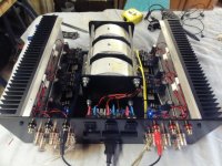
I have finished all the wiring and the assembly of the chassis and everything looks great. It weighs a ton.
I spent this morning listening to some music and its sounds awesome. Great to have it finished and working.
Big thanks to Peter Daniels and everybody who helped along the way.
Here's a few pics of the finished product without the top or front panel.
The only thing I have noticed is a low level buzzing an all channels, its not bad but it seems so get worse on the channels further away from the back panel. I can only assume perhaps the cables are picking up allot of RF/EMI as there length increases and that perhaps installing the top and front panel, essentially creating a Faraday cage may help.
As I said its not bad and cant be heard when playing music.
As it turns out I actually made a reasonably large mistake with the wiring from one side of the case to the other. I basically had all the cables color matched as they went from one psu board to the one on the other side of the chassis (think L & R channel).
But, the boards are oriented 180 degrees which meant the cable should have been also. I ended up frying 4 of the 8 rectifiers on one board, but did no damage to the other.
I fixed the wiring and replaced the rectifiers, tested again and hey presto, 6 working channels.
I have finished all the wiring and the assembly of the chassis and everything looks great. It weighs a ton.
I spent this morning listening to some music and its sounds awesome. Great to have it finished and working.
Big thanks to Peter Daniels and everybody who helped along the way.
Here's a few pics of the finished product without the top or front panel.
The only thing I have noticed is a low level buzzing an all channels, its not bad but it seems so get worse on the channels further away from the back panel. I can only assume perhaps the cables are picking up allot of RF/EMI as there length increases and that perhaps installing the top and front panel, essentially creating a Faraday cage may help.
As I said its not bad and cant be heard when playing music.
Attachments
A few more observations.
Having the three transformers each running a left and right channel and most importantly, switched independently, has turned out to be a great idea.
It seems that if the LM4780 has no input/output load(not sure which) it runs full power and produces a ton of heat.
So being able to run 2/4/6 channels as I choose/need means I can use the beast as a 2 channel amp without the other 4 channels wasting power and producing heat.
Wonderful job Thunk!!!
I used RG142 Coaxial cable for my input wiring and it works very well.
I have ZERO noise that I can hear out of my Audio Sector LM4780.
I'm now looking at changing to RG316 to reduce the size of the cabling and facilitate easier bending.
I also used a pre-twisted 16awg speaker cable that is jacketed.
They called it helical twist and it's made by Stinger, Monster & others (plus it looks nice).
- Status
- This old topic is closed. If you want to reopen this topic, contact a moderator using the "Report Post" button.
- Home
- More Vendors...
- Audio Sector
- 6 Channel Amp Wiring Advice