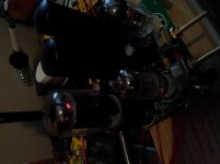
WOO HOO!!!! Got the rectifier to glow! I ended up shaving the polarizing keys off my tubes. Not sure if the board could have withstood all the mods. No worries, these tubes are now dedicated to r&d.
Output straight from the rectifier is 467VDC. Supply for the 6V6 tubes is 450VDC. Supply for the 12AX7s is 354VDC. These are too high,eh?
Output straight from the rectifier is 467VDC. Supply for the 6V6 tubes is 450VDC. Supply for the 12AX7s is 354VDC. These are too high,eh?
Attachments
The plate voltages are high.
6V6 should see no more than 350 volts. 12AX7 should see no more than 330 volts.
Thank you Frank. So I think I fried my 6V6s, most likely earlier. No continuity on the heater pins. Now I have to do some calculating to get the R values right and obtain some tube fodder
") Thanks also for the pin orientation comment - that was my original mistake.
Thanks also for the pin orientation comment - that was my original mistake.The RCA manual shows 350v for a 6V6. However, that is design specs RCA recommends. They are for polite designs like TVs and table radios. Leo Fender has been selling amps with 6V6 output stages running over 400 volts for over 50 years now, and they are not tube eaters.
Still 450v is too high.
Still 450v is too high.
Got a question while I wait for my new 6v6.
My rectifier is putting out 476VDC. Consequently all the plate voltages are high.
I measured 3.95mA running thru the first resistor in the chain - the 4.7k 2w. I think that is low and indicates that no current is being drawn by the two dead 6v6. Their cathode bias R's have no voltage at the pin, indicating lack of current.
My question is: Once the 6v6 tubes are installed, will they cause the rectifier to sag, thus lowering the output voltage?
Absolutely. You should wait until you can install the replacement 6V6 tubes.
At that time, you can determine the actual B+ voltage under operating conditions.
If you find that it's still a bit too high, you can always add a power supply choke before the first filter capacitor.
At that time, you can determine the actual B+ voltage under operating conditions.
If you find that it's still a bit too high, you can always add a power supply choke before the first filter capacitor.
ok first off My 5E3 has the diodes installed, but I think this is coz it had a 5ar4 rectifier(before i changed it to a 5y3). i dont think ya need em for the 5y3. secound dc voltage is to ground only and stand by switch must be closed to complete the circit. if you havn't yet installed other valves make sure to discarge the caps before in serting fingers they bite (belive me I know). hope this helps if you need any more info I hav My 5E3 sittin right here with the back off.
Thanks for the tips AB. As a matter of fact I did get shock from this thing. My first set of 6V6 were the metal can type. After I fried them a few days ago, I was probing with my meter and touched a case on one of them while also contacting the chassis. The case was somehow carrying B+ and I found that out the hard way! The fuse blew and the GFI on the wall also tripped. That's when I sat back and said that little prayer "dear God, thank you for letting me survive my own stupidity once again."
Well here's the report I promised. I got the cheapest electro-harmonix 6V6 I could find down at the guitar shop. Turned the amp on and got some mild screams and loud hum. Touching the pot shafts just right sorta helped. I grounded the pot cases and stuck a screwdriver in the input jack to short it. So now it can sit there at a pretty low hum and not scream. If I touch or move the shafts, loud hum can set in and then if I touch again once or twice it will reduce. This leads me to conclude that I need to seriously address the grounding. I gotta wait for my guitarist friend to give it a road test.
But first I have to work on some resistor values. I screwed up on the 6V6 cathode values when I split up the original single res. My plate voltages plummeted from the skyhigh figures of before. Drawing 11.7mA through that first 4.7k res. I think that's close to "normal".
And...this thing runs real hot due to the compact layout.
The case was somehow carrying B+ and I found that out the hard way! The fuse blew and the GFI on the wall also tripped. That's when I sat back and said that little prayer "dear God, thank you for letting me survive my own stupidity once again."
3 amp fuse at around 400 volts lucky ya hair didnt catch on fire lol
 .
.my layout is more traditional useing the stanard chassis but I hav saverlly moded the preamp feeding the output of channel one into the input of channel 2 to get more gain but swapping tube 1 for a 12ay7 as i play harmonica thru it, not guitar.
Attachments
Thanks for the tips AB. As a matter of fact I did get shock from this thing. My first set of 6V6 were the metal can type. After I fried them a few days ago, I was probing with my meter and touched a case on one of them while also contacting the chassis. The case was somehow carrying B+ and I found that out the hard way! The fuse blew and the GFI on the wall also tripped. That's when I sat back and said that little prayer "dear God, thank you for letting me survive my own stupidity once again."
Pin 1 is connected to the case on metal cased tubes like the 6V6 {nothing} and 6L6 {nothing}. On old Fender layouts you'll see pin 1 is grounded. On Fender blackface amps pin 1 is used as a place for the free end of the grid stopper. If you install a metal cased tube and the tube claw touches the case, you have no grid bias.
My pro guitarist friend played his fender strat immitation (still a real fender) on the amp today. He said the amp sounded very good even tho he had dead strings. Said he was surprised. Said to get new good quality pots. Said to bias the tubes. Said he felt a little voltage in the strings when I turned the tone low. Said the amp was quiet. It got about 3x-4x more hum when he plugged in he said the noise came from his guitar. Volume didn't bring on big loudness nor distortion and it basically didn't get that loud just low/moderate - slope was more horizontal. The volume control wasn't overly effective. Tone did some things but I was so excited that the dog worked right off the bat that I didn't make notes.
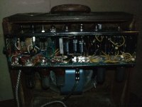
My own comments. If not for 2 minor mods at the outset, my board was good to go otherwise. I had to get creative mounting the pots. The replacements I got locally came without jam nuts - talk about unobtanium. So I c-clamped them on. So far I have not messed with any components but the pots. And that's about it. Frankenamp is born. I'm going to start trying to act like an EE and bias the tubes. Want to quiet the power as my scope shows it carries a little AC. Running cooler.
How do I make it so no voltage shows up on the strings!?!?!? Any comments appreciated.
Attachments
Your schematic shows a three wire grounded line cord. You should have continunity from the round pin (USA) to the chassis. This is usually a green wire with a yellow stripe. Also continunity from the chassis to the ground side of the input jack and to the strings on the guitar. If you do and there is still voltage on the strings, the problem is with the outlet you are plugged into, not the amp. Get one of those little gadgets with three lights that checks the outlet at a hardware store like Home Depot.
Thanks, I was suspicious of the wall power in my apartment, which is about 60-70 years old. There have been a few hacks into the wiring.
What about using an o-scope to check the outlet I'm using? I did that before and it showed a sine wave from one terminal to earth, and nothing on the other terminal. I think this is normal isn't it? Plus the outlet has a working GFI installed.
My grounding is solid re what you said, but I'm reviewing it.
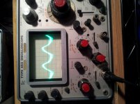
Of interest. Here is AC hum, no signal, at the second 12ax7. Right after the pots.
The first shows vol and tone at about 1-2 for both.
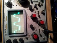
The second shows with vol and tone at about 7-8 for both.
That is probably why the volume response was so lackluster. This waveform is representative of the music that was flowing through it. Not good.
The first shows vol and tone at about 1-2 for both.
The second shows with vol and tone at about 7-8 for both.
That is probably why the volume response was so lackluster. This waveform is representative of the music that was flowing through it. Not good.
Attachments
Last edited:
What I'm going to do....
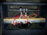
Proper biasing. My sense says start at the input and work forward. But since the amp showed well in the dog n pony show, and since I know for a fact (actually after the fact) that I totally screwed up on r values when I split the 6v6 cathode r, I'm going after that first. Gonna install a single 8W 250 ohm wirewound for both tubes.
Let me know if you want to see any scope analysis on some part of the circuit. I'll see if I can bring it up.
I did the resistor change mentioned in the previous post. Also attached one end of a resistor in the preamp I left dangling ooops!
I'll have to say it's pleasing to have it work so nicely. For lack of a guitar, I've been pumping MP3s through it and waiting for the solos! David Gilmore needs this amp haha. The volume is enough to start hurting and it stays nice and clear when pumped up. I subbed in some older used 12AX7 and the hum was muted and reduced by half. The Oscope shows typical audio waves, it's fun to try and isolate frequencies.
Well, I'm working on the next already. Its going to be a radical design!
Attachments
- Status
- This old topic is closed. If you want to reopen this topic, contact a moderator using the "Report Post" button.
- Home
- Live Sound
- Instruments and Amps
- 5Y3GT rectifier difficulty