To compensate for varying load and input voltage changes, the control IC uses Pulse-Width-Modulation (PWM). PWM is the changing the % of switching ON-to-OFF time to adjust the output voltage - and hence power - when the negative feedback senses a difference in the feedback signal compared to the reference. There's a lot going on here, and I recommend doing some studying on PWM and closed-loop systems so you understand it well before proceeding too much further. The datasheet of the control IC you use should explain the requirements too.
Also, using PWM in a closed-loop system, requires the transformer to be able to produce a higher-than-normal secondary voltage for times when the load is very high, or the input voltage is very low. For example, in your desired 12 Vin to 24 Vout system, you will probably need to wind the transformer with a 2.5:1 ratio. That way, in theory, the transformer will produce 30V with a 12V input. However, with a narrow PWM (ON for a brief period of time, and OFF for a long period of time), the supply will still only deliver 24V. By doing this, the closed-loop compensation, actually the op-amp within the control IC, will constantly monitor the output voltage, or a portion of it thanks to the opto-isolator and associated circuitry, and keep the output at 24V regardless of load or input fluctuations.
Through PWM and a transformer with a 2.5:1 ratio, the following will occur:
With 12V in, 24V out and a light load, the PWM pulses will be very narrow (like described above).
With 12V in, 24V out and a heavy load, the PWM will be fairly wide (half ON time, half OFF time).
With 10V in, 24V out and a heavy load, the PWM will probably be maxed out (the ON time being the entire 100% of its cycle (which is actually 50% of the total time - again, see PWM for details)).
In the example of 12V in and 24V out under heavy load, it would seem the output voltage would be higher than 24V because of the transformer ratio. But due to losses in the copper windings, the diodes, switch transistors, and the averaging of the output inductors, only 24V is delivered to the load.
Make sense? I hope this clarifies SMPS designs a little more.
My SMPS uses a fixed transformer ratio, no feedback, and the duty-cycle (PWM) is fixed. It relies on the fairly well-regulated, low impedance nature of a car's electrical system. Sure it fluctuates from 11 (with a dead battery or during engine starting) up to 14.4 (normal cruising with the alternator running everything), but the associated secondary voltage fluctuation is no problem for the amplifier. Also, the amplifier will produce more power at cruising speeds than with the engine off, but at normal or even high listening levels, it's never noticed. The trade-off for lower voltage or lower amplifier power at lower input voltages is simplicity in SMPS design.
Because of the simplicity of construction of an unregulated SMPS, I asked earlier about your regulation requirements. If you could tolerate +/- 10% change in secondary voltage, you could have a very simple supply!
You have reason DCPreamp, but my goal is to desing a SMPS that compensates the variations at the battery voltage with diffrent tipes of loads, I don't care if the power supply is a little bit less simple.
I've finished my design, I simulate it at LTSpice and works great ^^. Now I'm triying to put some protection, like temperature pritection, low battery, reverse input voltage or short circuit.
I've finished my design, I simulate it at LTSpice and works great ^^. Now I'm triying to put some protection, like temperature pritection, low battery, reverse input voltage or short circuit.
Cool! You know your reasons, so design away. I was just presenting one option, plus hoping to further explain transformer ratio and PWM.
Check the data sheet for the PWM driver IC you're using. Most PWM IC's, especially ones designed for push-pull topology, include under-voltage lock-out. The SG3526 I used includes UVLO of 8.5V, but it won't turn on until it hits 9.5V, so that gives is 1V of hysteresis.
For overcurrent and reverse-protection, just add a big power diode across Vin and a fuse inline with V+ (which you should always have anyway). If you look at the picture I attached of my SMPS, you can see an MR750 power diode for reverse protection and I have a 40A fuse inline.
For over-temp, you can go for a simple solution like a PEPI temp switch in-line with the remote-turn-on line and thermally connected to the chassis/sink. Or, you could use any number of thermistors or diodes used in conjunction with the voltage feedback. Doing that will cause the supply to begin folding back the PWM - and therefor output power - once it gets past a predetermined temp.
")
A couple things to consider:
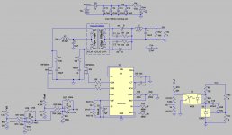
1) Diode D3 is in series with the entire supply's current. Is it placed correctly?
2) The IRF2804's may work as a single, because they are monsters, but paralleled devices are much more efficient. Still, given their 6.5nF Cin, you may want to consider something like a TC4429 dual FET driver.
3) Gate drive resistors are usually more like 10 ohms to eliminate parasitics.
4) Is the FF circuit for under-voltage detection? The SG3525 already has UVLO built in.
5) R32 has to dissipate almost 6 watts. Depending on the load, you may not need that much of an internal load.
Great job!
Sorry for don't specificate the design, I've change a lot of things.
The ouput voltage is 20v, not 24v. I thought about it and I prefered a SMPS of 400W power than 576W.
1)The diode D3 works perfectly, is a protection for reverse input voltage. what do you mean about if it's placed correctly?
2) you mean that its beter to use 2 parrallel MOSFET per side?
3) I will look at that.
4) the ff circuit changes the PWM duty cicle to make the output constant when the battery voltage is from 10v to 12v.
5) If the output voltage is 20v, R32 disipates only 4w.
I attached the files. For SG3525 model go LTspice model for SG2525/SG3525 - All About Circuits Forum and for TL431 go Components Library - LTwiki
Attachments
1) Sure D3 will work perfectly. However, what modeling doesn't warn you about is heat. With a standard diode, and the supply working at full power (400W), the diode will be dissipating ~36W! That's a lot of heat, not to mention you're losing a full volt of input voltage. Even if D3 was a Schottkey power diode, you'd still lose 0.3V and dissipate 10W. What's normally done is to put the diode in parallel with the input voltage with the cathode towards positive. That way it's out of circuit unless the battery is hooked up backwards - then it conducts blowing the fuse.
2) Yes. Paralleled FETs share current and improve performance.
4) The FF circuit is completely unnecessary. The feedback will compensate for input fluctuations & load. It just adds complexity and the potential for instability.
5) 4W of dissipation is still a lot. What savu said is correct - 1K or so is fine. For 4W of continuous dissipation you'll need a 10W resistor which is large and will require heatsinking.
For the efficiency of the supply, the model may be able to predict what it will be, but there are so many variables, I could only guess. Plus, efficiency will vary with load making it even tougher to predict. 80 to 90% is a realistic range.
You can use some of the ultra-low on-resistance, super high current devices, but they're expensive. Plus, using a single device-per-phase tends to decrease reliability and surge tolerance. In a low voltage, high power SMPS, the average current running the supply is just a fraction of the instantaneous surge-current experienced each time that FET switches on. That peak current can be many times higher than the average current. So a 200A device seems like overkill, it really is just adequate.
The IRF3703 looks like a great device, but is only rated 30V VBRDSS. With a push-pull SMPS topology, when one phase is conducting, the other device experiences 2*Vin, plus some noise spikes. Since a car's electrical system can run at 14.4V, 30V can be easily be across the off-device. I recommend 50V VBRDSS devices at a minimum.
What's done in industry, and I did in mine, is to use multiple devices paralleled so that each device is only switching a portion of the load. I used 3 X IRFZ42 FET's per transformer phase.
But ultimately it's up to you. You know your budget, plus you know, or will have to figure out, your PCB, the mounting technique of the devices and rectifiers, and the chassis your project will require. These criteria can also impact your device choice as the project advances.
I agree on the IRF2805 - a good choise. I myself could even try IRF2804...
I just finished a car SMPS that could interest you.
440W 99% efficiency.
PCB is only 6x15cm (2.4x6").
This might be a bit complex from the electronics point of view - it is full bridge dual core (E30).
But the transformers are therefore crazy simple.
Just one primary and one secondary. Which makes the utilisation of them ridiculously high, which results in a very high efficiency.
- Status
- This old topic is closed. If you want to reopen this topic, contact a moderator using the "Report Post" button.
- Home
- Amplifiers
- Power Supplies
- 576W SMPS for car audio amplifier