5687 update
hello to all the ppl that help me b4,
i need advice again..
ok..i have wired up pin 8 (CT)according to the circuit.
as for filament supply..this still confuse me guys..sorry for being so slow on picking it up..
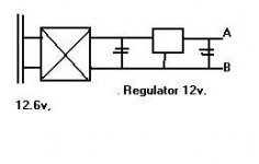
i have build a 12volts DC supply ..so how do i wire it up?? 12volts to pin 4 and the supply grd to pin 5? or 12volts to pin 4 and pin5?
i connect positive multimeter to pin 4 and neg to pin 5..reading 6.3volts only..this is for 12volt pin4..grd pin 5.
shouldnt it suppose to be 12volts?
thanks guys..appreciate it..
rgds
tone
hello to all the ppl that help me b4,
i need advice again..
ok..i have wired up pin 8 (CT)according to the circuit.
as for filament supply..this still confuse me guys..sorry for being so slow on picking it up..
i have build a 12volts DC supply ..so how do i wire it up?? 12volts to pin 4 and the supply grd to pin 5? or 12volts to pin 4 and pin5?
i connect positive multimeter to pin 4 and neg to pin 5..reading 6.3volts only..this is for 12volt pin4..grd pin 5.
shouldnt it suppose to be 12volts?
thanks guys..appreciate it..
rgds
tone
HEATERS
Hi,
Assuming you built according to the diagram you posted earlier...
Just connect the heater to pins 4 & 5 it does not matter which way around.
When you measure put the plus lead of your DVM at either pin at the minus lead at a ground point of your chassis.
You should now measure 12VDC approximately.
Cheers,")
Hi,
Assuming you built according to the diagram you posted earlier...
Just connect the heater to pins 4 & 5 it does not matter which way around.
When you measure put the plus lead of your DVM at either pin at the minus lead at a ground point of your chassis.
You should now measure 12VDC approximately.
Cheers,
HEATERS...IT IS WINTER HERE AFTER ALL
Hi,
So,it is working correctly now?
Sorry...this was confusing.
When you measure put the plus lead of your DVM at either pin and the minus lead at a ground point of your chassis.
Cheers,
Hi,
connect A to pin 4 and connect B to pin 5..measure by plus meter to either pin...negative meter to grd..right!..
So,it is working correctly now?
When you measure put the plus lead of your DVM at either pin at the minus lead at a ground point of your chassis.
Sorry...this was confusing.
When you measure put the plus lead of your DVM at either pin and the minus lead at a ground point of your chassis.
Cheers,
5687
hi frank,
is the chasis grd suppose to connect to the CT of the 200v-0-200v, if so im not getting any reading at all..i did the measure by plus to pin4/5 and minus lead to 200v CT..but if plus lead to pin4 and minus lead to pin 5 ..im getting 6.3volts..the tube did light up..but very deem..will keep u update..will try to hookup everything and hope there is sound..thanks frank..
appreciate it very much..
cheers,
rgds
tone
PREAMP
Hi,
I look forward to see a complete circuit diagram with B+ noted etc.
As it is there are a couple of points worth errr....pointing out:
1/The preamp inverts absolute phase with respect to its' input.
2/Output impedance is quite high since it's taken from the anode.
3/Volume control can be improved on with a switched attenuator.
The reason I ask is because I see ways to improve on the PSU and with the additinion of an OPT it would be a nice universal preamp.
Just some thoughts,
Hi,
Do you have a final power supply schematic written down to share with us?
I look forward to see a complete circuit diagram with B+ noted etc.
As it is there are a couple of points worth errr....pointing out:
1/The preamp inverts absolute phase with respect to its' input.
2/Output impedance is quite high since it's taken from the anode.
3/Volume control can be improved on with a switched attenuator.
The reason I ask is because I see ways to improve on the PSU and with the additinion of an OPT it would be a nice universal preamp.
Just some thoughts,
5687
Hi,
Paralelling the two sections of the tube would lower the output impedance but will not give you more gain.
Do you know the input impedance of the gainclones?
If these are // 'ed units the input impedance could be quite low.
Do you have too low gain from the the preamp?
You have to turn the volume way up to get satisfactory listening levels?
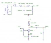
**Your PSU for the B+ is taxing the rectifier heavily now due to the high capacitance just in front of the 5K 5W resistor.
**The way the Cerafine caps are decoupled won't help all that much at higher frequencies,you could put some extra decoupling behind the last cap using a polyprop 0.100 mF and 0.010 mF in //.
Cheers,
Hi,
Paralelling the two sections of the tube would lower the output impedance but will not give you more gain.
Do you know the input impedance of the gainclones?
If these are // 'ed units the input impedance could be quite low.
Do you have too low gain from the the preamp?
You have to turn the volume way up to get satisfactory listening levels?
**Your PSU for the B+ is taxing the rectifier heavily now due to the high capacitance just in front of the 5K 5W resistor.
**The way the Cerafine caps are decoupled won't help all that much at higher frequencies,you could put some extra decoupling behind the last cap using a polyprop 0.100 mF and 0.010 mF in //.
Cheers,
5687 update
hi frank,
Do you know the input impedance of the gainclones?
If these are // 'ed units the input impedance could be quite low.
>its an inverted gainclone, "thorsten circuit".
Do you have too low gain from the the preamp?
You have to turn the volume way up to get satisfactory listening levels?
>err.. not really, but im using a 50k pot, i think the gain is ok, but i feel that i need a little bit more of power to get the tightness of bass at a reasonable listening level.."hope i dont confuse u"..::
Your PSU for the B+ is taxing the rectifier heavily now due to the high capacitance just in front of the 5K 5W resistor.
>any idea how to rearange the caps?..or should i take it out from the power supply? the poly caps is there cause i have it as spare in my drawer.
The way the Cerafine caps are decoupled won't help all that much at higher frequencies,you could put some extra decoupling behind the last cap using a polyprop 0.100 mF and 0.010 mF in //.
>ok..ill do that..
thanks.
rgds,
tone
BASS
Hi,
The 0.100 mF coupling cap is rolling off the bass response when coupled to the gainclones and should be a higher value.
If you have a good quality polyprop of at least 1 mF/400V I would try that first.
I haven't checked the input impedance of the gainclones yet but it would be wise to keep interconnect length to the bare minimum of say, 1.5 m.
PSU:
You could put the 100 mF/400V Chemicon behind the 5K resistor.
The choke filtered PSU would be nice but I feel a 10H choke would be more than adequate.
Cheers,
MAX. VALUE.
Hi,
Maximum value for C after the 6X4 is 10 mF,so you're O.K. with my suggestions.
Cheers,
Hi,
.(I need to check the max. allowed value for this arrangement)
Maximum value for C after the 6X4 is 10 mF,so you're O.K. with my suggestions.
Cheers,
frank help pls.
I do not know what happen, all a sudden the preamp not working..it works when there is no pot at input..when i put the pot at output..it works..any idea?..EXPERINCING DISTORTION... I didnt do anything at it..tot the pot was faulty..change that to a new one..same result..helpPPppPppp!!..i have tested the B+..voltage..the voltage when down to 45+volts only..b4 it was 90-100volts with tube on circuit ..any tought?..thanks.
tone
- Status
- This old topic is closed. If you want to reopen this topic, contact a moderator using the "Report Post" button.
- Home
- Amplifiers
- Tubes / Valves
- 5687 filament question