there is (in Babelfish J and pretty much every second amp on planet) inherent servo (input LTP) which is taking care of output offset , via NFB
you don't have that in mumbojumbopuckamp
though, if Papa sez and shows it's doable , no reason for doubts
True.
I think Generg's biasing circuit achieves somewhat similar effect, but I don't know if Papa intended to do it that way based on his schematic.
Either way, I'm a sucker for punishment, so I'll do it exactly how Papa has drawn it to start with.
Last edited:
He sez, but first time no picture,
First picture comes from 2picodumbs......)

Great place, big ideas!
Good luck!
Could be that he could think more clearly once he relaxed and got a load off his mind.
[special=]%[/special]
No. I will still try the most basic circuit to satisfy my own curiosity.So Picodumbs, did you change your mind about trying the stock circuit?
Testing of Optocoupled CCS Part 1 Complete
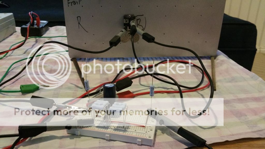
Completed optocoupled ccs circuit on breadboard, all is functional. Mosfet turns on nice and slow.
With R5=20k I am getting approximately 2.7A.
I can do a short video showing soft turn on of circuit.
Next stage, I will test for stability of CCS over extended period as heatsink warms up. This shouldn't need further testing but I will do it for the low in faith, and curiously minded people.
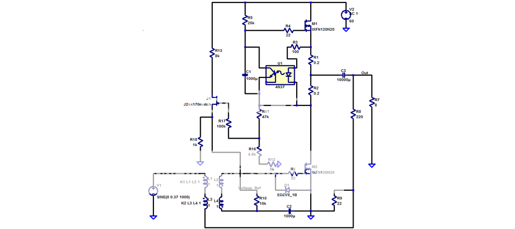
The test circuit is below.
Completed optocoupled ccs circuit on breadboard, all is functional. Mosfet turns on nice and slow.
With R5=20k I am getting approximately 2.7A.
I can do a short video showing soft turn on of circuit.
Next stage, I will test for stability of CCS over extended period as heatsink warms up. This shouldn't need further testing but I will do it for the low in faith, and curiously minded people.
The test circuit is below.
Here is video, showing turn on behaviour of CCS circuit.
https://www.youtube.com/watch?v=BPKOTdmNhQ8
https://www.youtube.com/watch?v=BPKOTdmNhQ8
Last edited:
Yes nice video, thanks much Pico. It's good to see that it is behaving well.
Now I'm excited to see how it will behave in the complete circuit, I hope it works.
Some others had problems with it so maybe thier problem was in the other part of the circuit. Maybe something was feeding back and causing problems.
Now I'm excited to see how it will behave in the complete circuit, I hope it works.
Some others had problems with it so maybe thier problem was in the other part of the circuit. Maybe something was feeding back and causing problems.
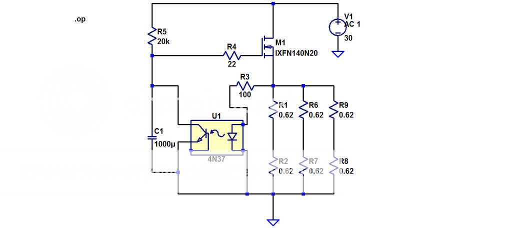
Now tested with 30V supply without current limiting.
With R5=10k, I'm getting a stable 3.06A
Changing R1 and R2 to 0.56Ohms gets me to 3.14A, so in the ball park of where Papa said it should be.
I'll build the rest of the circuit to see how it behaves.
we are all impatiently waiting for your results
- Home
- Amplifiers
- Pass Labs
- 50w Single-Ended BAF2015 Schade Enabled