zeus_threat said:Hi i've simulated and prototyped this amp.
Seems to work fine .
Any comments for improvement are welcome
Looks all perfect, to me.
")
I think you could build this amplifier.
Maybe an upgrade to TIP35/36 or MJE15024/25 in output stage.
It was long ago since really good amplifiers stopped using 2N3055 / TIP3055.
I guess you used them only for simulation.
TIP35 and TIP36 are my favourites, if you do not want to use TO3.
They are still lower price, but can take considerable powers.
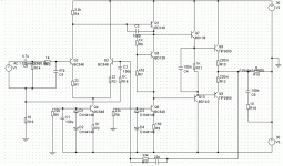
Input stage is 0.3/0.3 mA and the balance is 50-50 =good.
Second stage, VAS is about 4 mA.
Using BC546 and BD140 ?????
Of course you should change BD140 to BC556.
At only 120 mWatt ( 4mA x 30 Volt ) BC556 can still work alright.
An interesting alternative may be BC639 - BC640 for this second stage.
They are 1.0 Watt TO92, while BC546/556 is only 0.5 Watt.
Because you use BD140-BD139 as Drivers for output
you can do good with TO92 in VAS stage, if they can take 60 Volt.
Personally I would increase the minimal current in Q7/Q10 drivers.
This is the current thorough R11 ( 1 K ).
I know most would use lower current, like you.
I would make this current ~10-50mA!!!, for example use R11= 100 Ohm.
----------------------------------------
Finally, you have a very good amplifier circuit there.
Some small adjustments only.
and you can start putting it together- In Real.
Will you use PCB .. or will you try hard wiring
= solder components directly to each other?
lineup
======================================
Datasheets PDF download
TIP35 & TIP36 data - 125 Watt Power Transistors
http://www.bourns.com/pdfs/tip35.pdf
http://www.bourns.com/pdfs/tip36.pdf
Hi,
Nice work, I prefer Lin topology too.
About modifications broadly speaking I agree with Lineup.
So:
- scale down R11 to 100/220 ohm
- bypass Q5 with a 47nF cap
- omit R1 and R2, or change them to 100 ohm (they need to be: R=26/I(mA) )
- use a resistor + a trimmpot instead of R7 for proper adjust of bias (20-100mA)
- if amp is stable without R17 (it WILL be stable!), then omit that
- bypass supply with a 10uF-470uF elko, and with a 100nF-470nF cap
- scale down input cap to 2.2uF, or increase C2 to 220uF (time constant in the feedback need to be higher than at input)
- use BC639 or BD139 instead of BC645 in the VAS stage (Q6)
- i wouldn't upgrade output transistors. TIP2955 and TIP3055 will do the job fine.
Re: a question
Hi,
C2 is for blocking DC in the feedback.
R16 is the part of the feedback loop. It determines the gain (it's 27dB), and with C2 it forms a high-pass filter.
R18 is for setting back ground loop.
Gigapod said:Hi zeus_threat,
Thanks for posting your schematics with easy-to-find components.
I have a question:
what are C2 R16 R18 for?
Thank you.
Hi,
C2 is for blocking DC in the feedback.
R16 is the part of the feedback loop. It determines the gain (it's 27dB), and with C2 it forms a high-pass filter.
R18 is for setting back ground loop.
Hi Gigapod,
So let's start.
Lin topology? In audio this topology [differential amplifer (long taled pair-LTP) + voltage amplifier stage (VAS) + driver and output stage] is called 'Lin". Sorry, I don't know where this name came form.
This bulidup remindes me to the early RCA designs from the USA. Maybe "Lin" was a designer at RCA corporation?
About R11: the alue determines the idle current of the driver transistors (I=1,2/R). 10mA is OK, so R11 need to be about 100 ohm.
About bypassing Q5: sometimes the Vbe multiplier (formed by Q5+R6+R7) tends to oscillate. A small cap stops oscillation.
About VAS transistors: at 35V supply Q6 will dissipate 0,15W. That causes that the transistor will be 100°C hot at 50°C ambient temperature. That's not enough safe for me.
edl said:
- use BC639 or BD139 instead of BC546 in the VAS stage (Q6)
- i wouldn't upgrade output transistors.
TIP2955 and TIP3055 will do the job fine.
Yes, think edl is very right here.
He did also look a bit closer than I did at your circuit.
Consider his advice. Try them out in your simulations, if you can.
Also after checking the output TIP2955/3055 vs. TIP35C/36C
I have to admit, TIP2955/3055 might work as well.
Maybe even slightly better at moderate powers
due to possibly a bit higher gain, HFE, than TIP35 has.
The only small advantage for TIP35 is lower heat resistance.
1.0 C/W versus 1.4 C/W for TIP2955.
This means TIP35 will work at lower temperature than TIP2955/3055
at higher power. If same size heatsink.
But if you use a bit larger heatsink for TIP2955/3055
there will be no difference.
And the margin for overheating will be good.
But for more power = more heat, you may want to use TO3 devices.
Like the MJ15024 / MJ15025 ( MJ15022 / MJ15023 ) I mentioned.
Regards
lineup
Hi edl,
Thank you very much for taking the time to explain the circuit, your knowledge is very impressive.
Lin perhaps was the abbreviated form for "Linear"? So apparently this became a "classic" topology for amplifiers?
I am attaching the schematics for an old (1980) amplifier 45W RMS on 8 ohms. It has a very similar circuit topology if I understood you well.
Only it seems they used PNP transitors for the LTP.
I assume R726 is for setting bias current, but I don't understand the function of Q722/Q724.
Your comments are more than welcome.
Thank you.
Attachments
Hi,
Q722 and Q724 forms output protection.
When the amplifier output is short circuted, the current across the output transistor starts increasing. When the voltage drop across the emmiter resistors (R750 and R?) reaches 0,7V, the protection transistor opens, and "pulls down" the base of the driver transistor. Then the accesion of the current stops, and will be constant.
Then the current flowing through Q732 and Q730 is determined by the following equation: I=0,7V/Re/2. Here it equals 0,7/0,22/2= 1,6A.
Dividing by 2 is because the current flows only in one half-period.
I hope I was enough clear to understand (my english is not the best ).
Q722 and Q724 forms output protection.
When the amplifier output is short circuted, the current across the output transistor starts increasing. When the voltage drop across the emmiter resistors (R750 and R?) reaches 0,7V, the protection transistor opens, and "pulls down" the base of the driver transistor. Then the accesion of the current stops, and will be constant.
Then the current flowing through Q732 and Q730 is determined by the following equation: I=0,7V/Re/2. Here it equals 0,7/0,22/2= 1,6A.
Dividing by 2 is because the current flows only in one half-period.
I hope I was enough clear to understand (my english is not the best
).Hi gigapod
HC Lin built the first quasi complementary output stage while at RCA.
zeus-threat's amp is a differential, commplementary update of the Lin.
I agree with edl, TIP3055/TIP2955's should work. In fact the crossover performance (as I have simulated using 2N3055/MJ2955 (but I had to modify the ON semi models) seems to be quite good at moderate currents (~50 mA).
BD140's still good. Think that BC640's are same device but in TO-92 so aren't so good for dissipation.
Data sheets for 2N3055 and BD139/140 have changed over the years. 2N3055 now about 3rd or4th iteration, BD140 now has higher gain as standard.
cheers
John
Hi edl,
You were very clear and your english is excellent. And your explanation is clear as crystal too, thank you very, very much.
I was thinking why this amplifier does not have a protection relay, and you have provided the explanation: the protection is electronic.
Going back to the amplifier circuit of the OP, do you think a similar circuit could be added for short-circuit protection?
john_ellis said:Hi gigapod
HC Lin built the first quasi complementary output stage while at RCA.
zeus-threat's amp is a differential, commplementary update of the Lin.
Wow, thank you John. I think amplifier design history is fascinating.
It seems good designs and solutions survive for a long time, of course because they are good to begin with.
If you use that method of current limiting with the two transistors, which is known as 'foldback current limiting', make absolutely sure to use the diodes across the output transistors from power supply to output as seen in the original schematic. This is because with a reactive load, such as a speaker, if the current limiting kicks in during music playback, the speaker can pull the output transistors into reverse bias and destroy them. The diodes simply drain this current into the power supply and prevent the transistors being cooked should such a thing happen.
It sounds really nasty when the current limitin kicks in, but it will save a power amp from shorted output conditions if designed and implemented properly.
Read this if you would like some in-depth information on the topic.
Testing the Limits
It sounds really nasty when the current limitin kicks in, but it will save a power amp from shorted output conditions if designed and implemented properly.
Read this if you would like some in-depth information on the topic.
Testing the Limits
unclejed613 said:make R7 a variable to adjust your bias. if the wiper gets oxidized and goes open, it turns the bias transistor full on, shutting down the bias, and you don't burn up your outputs. also Q5 goes on the same heatsink as the output transistors....
Yes, as I already wrote:
- use a resistor + a trimmpot instead of R7 for proper adjust of bias (20-100mA)
Hi Duo,
It sounds really nasty when the current limitin kicks in, but it will save a power amp from shorted output conditions if designed and implemented properly.
I can't agree, because this type of protection is active ONLY at short circut. At high currents, at high output power it will never go active, because the protection transistors cannot open. So you can't hear the disturbance of the current limit in the music.
Maybe it's better to call this configuration "short circut protection" instead of "current limiter".
All the best,
This depends entirely on the design of the amplifier and the impedance and phase angle of the load.
It is quite common for this system to activate in normal usage if you have highly reactive speakers or are using speakers of too low impedance.
Another reason I mention this is because I have experienced and proved it to happen with various consumer amplifiers employing that aforementioned limiting strategy.
- Status
- This old topic is closed. If you want to reopen this topic, contact a moderator using the "Report Post" button.
- Home
- Amplifiers
- Solid State
- 50W amp