I'm wondering if anyone has any idea why I see a 50hz spike when using a ADuM7440 SPI isolator IC between a micro-controller and a DAC. I don't have much experience with isolators but just read the datasheet and designed the PCB myself. I have two 5V PSUs where I intended to use one for the DAC IC and one for the Arduino microcontroller with the ADuM7440 isolating them.
These are my observations:
1x 5V PSU with ADuM7440 bypassed = Good
2x 5V PSU with ADuM7440 for isolation = 50hz spike.
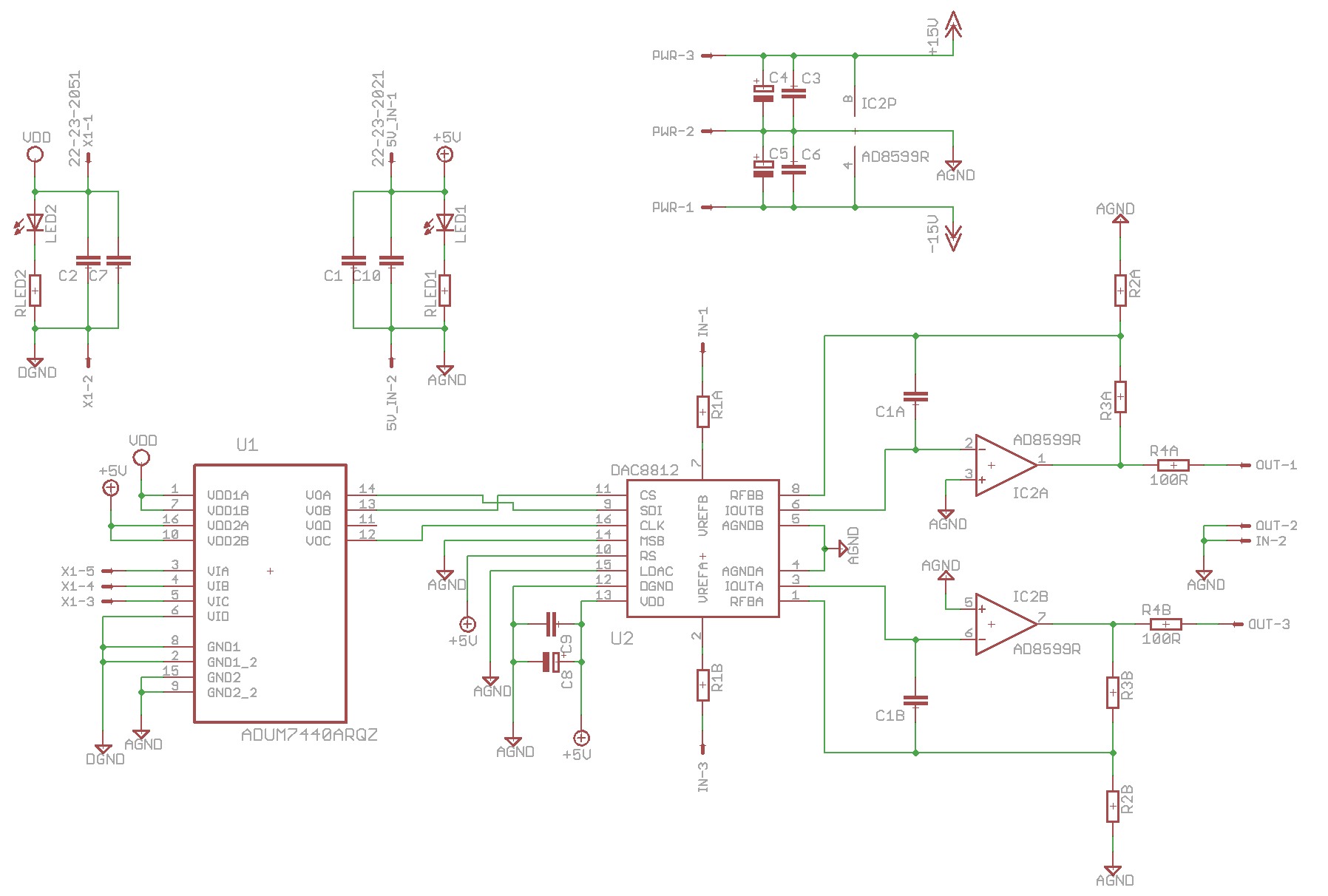
Here is the schematic:
http://www.diyaudio.com/forums/atta...g-switches-multiplying-dac-mdac-schematic.jpg
To bypass the ADuM7440 IC I just connected the VDD/5V and GNDs from either side of the IC.
Attached is the layout and two graphs showing the 50hz spike.
Did I make some mistake? Poor layout? It just seems weird that either PSU on its own measure fine but as soon as I use the IC to isolate I get a 50hz spike 😕
These are my observations:
1x 5V PSU with ADuM7440 bypassed = Good
2x 5V PSU with ADuM7440 for isolation = 50hz spike.
Here is the schematic:
http://www.diyaudio.com/forums/atta...g-switches-multiplying-dac-mdac-schematic.jpg
To bypass the ADuM7440 IC I just connected the VDD/5V and GNDs from either side of the IC.
Attached is the layout and two graphs showing the 50hz spike.
Did I make some mistake? Poor layout? It just seems weird that either PSU on its own measure fine but as soon as I use the IC to isolate I get a 50hz spike 😕
Attachments


I would have to guess the problem is with the power supply.
If it was a problem with the board I would expect the spike to
be present all the time.
Try swapping the two supplies and see if the spike goes away.
What power supplies are you using?
Are you able to reverse the phase of the AC input for one of
the supplies?
If it was a problem with the board I would expect the spike to
be present all the time.
Try swapping the two supplies and see if the spike goes away.
What power supplies are you using?
Are you able to reverse the phase of the AC input for one of
the supplies?
I tried this. Either power supply on its own doesn't produce the spike. I also tried a battery supplying the Arduino and my 5V PSU powering the DAC but still get the same spike.Try swapping the two supplies and see if the spike goes away.
Two of these.What power supplies are you using?
You mean just swapping L and N on the mains side? I just tried this, still a spike!Are you able to reverse the phase of the AC input for one of
the supplies?
I also thought it might just be interference radiating through the air when having 3x power supplies in the same small enclosure so I tried it with a single 5V PSU and the second one still powered up and in the case but not connected, still the spike though.
Very interesting, i found exaclty the same problem with an ADUM4160 USB isolator, i have two different boards and one of them has a 50hz spike, the other doesn't. I assumed the issue was due to the 12" of cable between the power supply and isolator module. The board without the issue has an onboard rectifier and gets AC power directly from a wall wart, where as the noisy one has a power supply in a separate enclosure.
Yeah. It's on and connected for all measurements. It controls the DAC so is required.Hi,
When you see the spikes the micro it is running?
i have two different boards and one of them has a 50hz spike, the other doesn't.
I'm guessing I had something to do with one of those...😉
50Hz is the mains frequency in the UK is it not?
The puzzle is why the problem only happens with two power supplies.
Can you power one side with a battery?
At least we can figure out which side to concentrate on.
My bet would be on the DAC side.
The puzzle is why the problem only happens with two power supplies.
Can you power one side with a battery?
At least we can figure out which side to concentrate on.
My bet would be on the DAC side.
Hi,
I asked the question because when you send the data from the micro to the dac you have to clock it. You are sending 16 bits to the dac. The clock would radiate noise when clocking the data to the dac. You can do a check to see if it is coming from the communication between the dac and the micro. Connect everything and program the micro to halt and see what happen.
I asked the question because when you send the data from the micro to the dac you have to clock it. You are sending 16 bits to the dac. The clock would radiate noise when clocking the data to the dac. You can do a check to see if it is coming from the communication between the dac and the micro. Connect everything and program the micro to halt and see what happen.
The clock would radiate noise when clocking the data to the dac..
While this is possible, it would be at a much higher frequency than
50 Hz.
50 hz is interesting. I would expect to see 100 hz residue as the rectified line voltage is 100 hz. You are using a full wave bridge or half wave? Is the ripple freq 100hz?
I'm guessing I had something to do with one of those...😉
Yup, yours would be the quite one 😉
The default SPI clock for the Arduino is 4Mhz 😉 I could try disconnecting the SPI lines after all the parameters have been set and then see how it measures though?Hi,
I asked the question because when you send the data from the micro to the dac you have to clock it. You are sending 16 bits to the dac. The clock would radiate noise when clocking the data to the dac. You can do a check to see if it is coming from the communication between the dac and the micro. Connect everything and program the micro to halt and see what happen.
Yeah I can power the Arduino with a battery and I still get the spike.Can you power one side with a battery?
At least we can figure out which side to concentrate on.
My bet would be on the DAC side.
Not sure! This is my rectifier: DFL1508S-E3/45 - VISHAY - BRIDGE RECTIFIER, 1.5A, 800V | Farnell UK50 hz is interesting. I would expect to see 100 hz residue as the rectified line voltage is 100 hz. You are using a full wave bridge or half wave? Is the ripple freq 100hz?
The spike is present in both of your plots, just the level changes. The first one has around -119dB relative to FS, the second around -134dB. Assuming we're looking at 1VRMS for the 0dB reference point these signals are in the region of 1uV and 200nVRMS respectively.
Given the absence of harmonics my first guess would be capacitive coupling from the 50Hz mains. Let's get some handle on the numbers involved - at 50Hz a 1pF capacitor looks like 3Gohms - if your DAC has a 100ohm output impedance this makes a 30,000,000:1 potential divider. So with 240VRMS on the input to this, the output would be 8uV. It seems therefore that your spike at -119dB could be due to just (very roughly) 0.1pF of stray capacitance to mains.
Given the absence of harmonics my first guess would be capacitive coupling from the 50Hz mains. Let's get some handle on the numbers involved - at 50Hz a 1pF capacitor looks like 3Gohms - if your DAC has a 100ohm output impedance this makes a 30,000,000:1 potential divider. So with 240VRMS on the input to this, the output would be 8uV. It seems therefore that your spike at -119dB could be due to just (very roughly) 0.1pF of stray capacitance to mains.
OK! How would I stop that? Shielding?It seems therefore that your spike at -119dB could be due to just (very roughly) 0.1pF of stray capacitance to mains.
-134dB, sure! I don't have a number in mind but if I can change the design or make other changes to make it better then I will.
-134dB, sure! I don't have a number in mind but if I can change the design or make other changes to make it better then I will.
With all due respect, but what do you want to achieve... a perfect measurement? The -119db is inaudible and with the sensitvity of the human ear at that frequency you'll probably never hear it no matter how much you cranck the volume up..
Now ta further reducing the peak.
Stray capacitance is usually caused by the construction of your setup. So you could resort to srparate the psu from the DAC if possible.
Also you could be plagued by a minor grounding issue.
So perhaps a pic or two might be helpfull assessing the situation.
I know -119 is quite low but sometimes it measures near -100, not sure why it changes though. To be honest my main reason for persuing this issue is because I'd like to learn why it happens out of curiosity, not because I'm obsessed with measurements. And I also thought I'd made some mistake with my layout or something else obvious since the difference in measurements was so noticeable.With all due respect, but what do you want to achieve... a perfect measurement? The -119db is inaudible and with the sensitvity of the human ear at that frequency you'll probably never hear it no matter how much you cranck the volume up..
Thanks! My setup wiring is a bit of a mess so perhaps I'll fix that and put some internal shielding in place between the analog circuits and the mains/PSUs and then redo the measurements.Stray capacitance is usually caused by the construction of your setup. So you could resort to srparate the psu from the DAC if possible.
Also you could be plagued by a minor grounding issue.
So perhaps a pic or two might be helpfull assessing the situation.
- Status
- Not open for further replies.
- Home
- Source & Line
- Digital Line Level
- 50hz spike when using ADuM7440 SPI isolator IC between a micro-controller and DAC