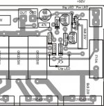
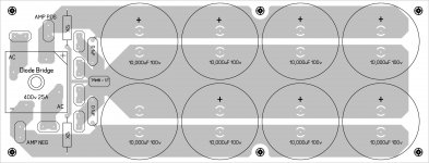
Regulated PSU for dual B500
mean while can you post a circuit board design for a dual B500's PSU
thanks...
Hi Miles....thanks for all your help and designs...I have a question, this Regulated PSU you listed, is similar to the PSU-5 that was listed some time ago, but this design has two more 10000uF caps and another pair of 2SC5200's....do you have a updated circuit board design that will carry these last modifications.....I am still going to use the Amp Protect board, I just want clean power supply. I am build a pair of B500's back into a MC2 T1000 amp case...it failed late last year after several years of abuse in a night club....it has a good toroidal tranny and other bits, but I would rather rebuild it using all APEX designs.....will post pics as things happen.This Regulated PSU can be use for B500.
mean while can you post a circuit board design for a dual B500's PSU
thanks...
toroidal tranny..
hey gooseneck....was not going to 'unwind' the tranny....am going to use it as it is....as I said 'it is from a T1000 MC2 amplifer' that burnt out...and is too costly and difficult to repair, so am going to use all the hardware from the T1000 to build a dual B500...ok..the T1000 is a dual 500w / 4ohm amplifier, so the tranny is just right for the project, the PSU gives 90v +-, 15v +- and 24v.no its not a toroid transformer...difficult to unwind...
B500 with clip LED
In the dual B500 project I am working on, the chassis is ex MC2 T1000, and already has peak LED's on the front plate with a plug in wire loom, it also has power on indicator LEDS and signal and bridge indicators...will figure how to wire those up to, meanwhile I have something to wire the peak LEDS to.....
thanks Miles
Hi Miles...was looking for a 'clip LED' addition to the B500 and found this circuit you posted the other day...even went back into my files and modified the pc board layout to accomodate the clip LED....and the component layout.Add LED in series with LED integrited in NSL32, and you have clip/limit indication.
Regards
In the dual B500 project I am working on, the chassis is ex MC2 T1000, and already has peak LED's on the front plate with a plug in wire loom, it also has power on indicator LEDS and signal and bridge indicators...will figure how to wire those up to, meanwhile I have something to wire the peak LEDS to.....
thanks Miles
Attachments
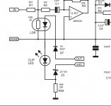
Hi Miles...was looking for a 'clip LED' addition to the B500 and found this circuit you posted the other day...even went back into my files and modified the pc board layout to accomodate the clip LED....and the component layout.
In the dual B500 project I am working on, the chassis is ex MC2 T1000, and already has peak LED's on the front plate with a plug in wire loom, it also has power on indicator LEDS and signal and bridge indicators...will figure how to wire those up to, meanwhile I have something to wire the peak LEDS to.....
thanks Miles
'Bridge led' can be add in series with 'power led' and shorted with bridge switch...
Attachments
B500 with led indicators...
thanks Miles, will now work on a small 'add on' board to power up the LEDS'Bridge led' can be add in series with 'power led' and shorted with bridge switch...
B500 with LEDS...
actually am going to add these extra LED's to the existing B500 PCB, bit of a squeeze but hey, why not, if any one else is trying this, please post your results...thanks Miles, will now work on a small 'add on' board to power up the LEDS
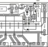
B500 PCB with Clip, Signal & Power LEDS
Hey Miles, could you check out this possible PCB layout and tell me if it is ok...a bit of a squeeze and all done in MSPaint...cause none of the pcb & circuit design programmes can read JPEGS and I did not feel like redrawing the entire circuit just to get these LEDS onto the PCB...so I did it the old fashioned way.
Wish you would load up a design file, so the PCB could be altered properly...it would also give a better image for etching.
Thanks for adding the LEDS to the B500 circuit design, I am now looking forward to building these B500's, no problems with component supply here in Singapore.
After looking over all the PSU's and Protection designs, I am going with a PSU-7, with out regulated dc, but with soft start.
I may be called a fool, but in considering my choice...I studied 'PA Protect' and wondered when I would use it...short circuit protection I have never had a need for, I don't over load my speakers and have never burnt any out...thermal protection is not issue cause the fans I have and the heatsinks work well and have a heat sensor built in already, and I did not want a pair of boards cluttering up my amp casing...so I went with the one piece board of the PSU-7. Different strokes for different folks I guess.
Any way hope you other guys have fun doing what you are doing. Here is the busy end of the B500 board with LEDs..the rest of the board did not change....looking forward to your comments Miles.
ciao....
actually am going to add these extra LED's to the existing B500 PCB, bit of a squeeze but hey, why not, if any one else is trying this, please post your results...
Hey Miles, could you check out this possible PCB layout and tell me if it is ok...a bit of a squeeze and all done in MSPaint...cause none of the pcb & circuit design programmes can read JPEGS and I did not feel like redrawing the entire circuit just to get these LEDS onto the PCB...so I did it the old fashioned way.
Wish you would load up a design file, so the PCB could be altered properly...it would also give a better image for etching.
Thanks for adding the LEDS to the B500 circuit design, I am now looking forward to building these B500's, no problems with component supply here in Singapore.
After looking over all the PSU's and Protection designs, I am going with a PSU-7, with out regulated dc, but with soft start.
I may be called a fool, but in considering my choice...I studied 'PA Protect' and wondered when I would use it...short circuit protection I have never had a need for, I don't over load my speakers and have never burnt any out...thermal protection is not issue cause the fans I have and the heatsinks work well and have a heat sensor built in already, and I did not want a pair of boards cluttering up my amp casing...so I went with the one piece board of the PSU-7. Different strokes for different folks I guess.
Any way hope you other guys have fun doing what you are doing. Here is the busy end of the B500 board with LEDs..the rest of the board did not change....looking forward to your comments Miles.
ciao....
Attachments
Last edited:
Hey Miles, could you check out this possible PCB layout and tell me if it is ok...a bit of a squeeze and all done in MSPaint...cause none of the pcb & circuit design programmes can read JPEGS and I did not feel like redrawing the entire circuit just to get these LEDS onto the PCB...so I did it the old fashioned way.
Wish you would load up a design file, so the PCB could be altered properly...it would also give a better image for etching.
Thanks for adding the LEDS to the B500 circuit design, I am now looking forward to building these B500's, no problems with component supply here in Singapore.
After looking over all the PSU's and Protection designs, I am going with a PSU-7, with out regulated dc, but with soft start.
I may be called a fool, but in considering my choice...I studied 'PA Protect' and wondered when I would use it...short circuit protection I have never had a need for, I don't over load my speakers and have never burnt any out...thermal protection is not issue cause the fans I have and the heatsinks work well and have a heat sensor built in already, and I did not want a pair of boards cluttering up my amp casing...so I went with the one piece board of the PSU-7. Different strokes for different folks I guess.
Any way hope you other guys have fun doing what you are doing. Here is the busy end of the B500 board with LEDs..the rest of the board did not change....looking forward to your comments Miles.
ciao....
You forgot 47k...
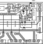
B500 amp with LEDS...cntd
thanks Miles, a second pair of eyes is always good for checking stuff...
actually on my pen sketch drawing that 47k is there and I even made space for it on the layout drawing by moving the 100uf cap out of the way, but forgot to put it in the 47k.....here it is now...thanks for your time Miles...ciao
You forgot 47k...
thanks Miles, a second pair of eyes is always good for checking stuff...
actually on my pen sketch drawing that 47k is there and I even made space for it on the layout drawing by moving the 100uf cap out of the way, but forgot to put it in the 47k.....here it is now...thanks for your time Miles...ciao
Attachments
Yes I am a DIYer...
just in case someone thinks I may be out of place here...I am a DIYer and have been for years...for this reason I am rebuilding one of my amps..with a couple of B500's as you will read here...and why you may ask...
I am a DJ by night and a design engineer by day..have been working this way since 1977...three and four nites a week originally untill about 2002, when traveling for my day job slowed me down, but did not stop me...now in Singapore work most weekends, doing weddings, parties, birthdays, events in fact any thing that needs good music...and I use double 15 inch speakers with horns....I used to use JBL JRX215's, but left those in NZ when I came out here to Singapore, now I use Behringer P2520's which are double 15's and horn also, I carry my own gear and so have built compact racks to carry mixer, digital Cortex music players, and of course Amp...I run a ELS P300 on one rig (450w into 4r) and used to run the MC2 T1000 on the other rig (500w into 4R) the speakers are rated at 900w peak and so have never had problems with things blowing up. This MC2 amp was bought at auction second hand and had had a hard life in a club....I will be rebuilding it using a pair of B500's running on the original power supply in the MC2....80v supply which should give me 450w to 500w like my other amp...I find this power is plenty enough for the venues I play in, and for the bigger gigs, I just run all four speakers and two amps and subs...giving me double the power of one rig and still sounding sweet.
I have been doing DIY projects since I was a teenager, used to fix the valve amps in a band I was in when I was 15...worked with bands and disco gear ever since, built my first solid state amp set back in 1977 using Sanken hybrid amps...used 6 x 50w units, with a DIY inbuilt crossover network and for speaker cabs which I built...I used 15" for bass in a vented cab, a 12" in a flared cab for mids and a Altec Lansing horn for the tops..it sounded great and work for years, but was a lot to carry.
In the early 90's I built a bunch of 250w mosfet amps and they worked well, they are still working now, somewhere in NZ.
I went to double 15's and horn in the mid 80's and have used them ever since...I have had satelite and sub combos as well, but found they were harder to transport...found they were great for vocals in a band situation, but prefer the double 15's on the dance floor for good heart thumping music, where it counts....can still add subs as well, but do not always have the room to transport them. No matter. Yes I am a DIYer..and I love it, I very rarely have things break down, I just keep updating gear as new technology comes on the market...
The motto I have is..if it ain't broken, don't fix it, just leave it be.
ciao for now...gotta go get ready for a party tonight....lol
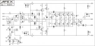
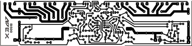
B500 with LED's
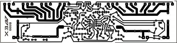
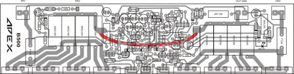
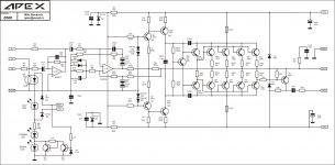
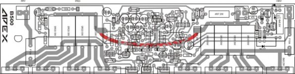
Ok here is modified B500 circuit that Miles generated and then all the components overlaid over the pcb with the 47K as it should be, and then the copper side of the pcb....would like to see what others think of this?
I am now shopping for all I need, a lot of the R's and some of the C's will come out of my stock on hand, the rest I will get from Sim Lim Square in Singapore.
thanks Miles, a second pair of eyes is always good for checking stuff...
actually on my pen sketch drawing that 47k is there and I even made space for it on the layout drawing by moving the 100uf cap out of the way, but forgot to put it in the 47k.....here it is now...thanks for your time Miles...ciao
Ok here is modified B500 circuit that Miles generated and then all the components overlaid over the pcb with the 47K as it should be, and then the copper side of the pcb....would like to see what others think of this?
I am now shopping for all I need, a lot of the R's and some of the C's will come out of my stock on hand, the rest I will get from Sim Lim Square in Singapore.
Attachments
Ok here is modified B500 circuit that Miles generated and then all the components overlaid over the pcb with the 47K as it should be, and then the copper side of the pcb....would like to see what others think of this?
I am now shopping for all I need, a lot of the R's and some of the C's will come out of my stock on hand, the rest I will get from Sim Lim Square in Singapore.
You have mistake on your pcb: power led catode must be connect to signal led anode not to gnd.
hello apex sir
for stereo can i use this psu for b500 with 55v,0,55vac?
Yes, you can.
Regards
- Home
- Amplifiers
- Solid State
- 500W PA amplifier with Limiter