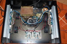
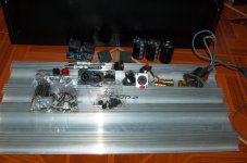
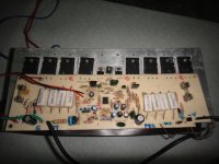
preparing to mount on chassis
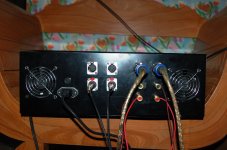
Done testing with the B500 now im preparing to mount on huge chassis,and more hand work for mounting the connector and terminals..more pictures attach
TY APEX for the LOGO
Done testing with the B500 now im preparing to mount on huge chassis,and more hand work for mounting the connector and terminals..more pictures attach
TY APEX for the LOGO
Attachments
Last edited:
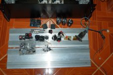
Done testing with the B500 now im preparing to mount on huge chassis,and more hand work for mounting the connector and terminals..more pictures attach
APEX logo for your amp and speakers,
Regards
Attachments

apex i had a few queries..
1. 4 pair of o/p is it enough for 500W @ 4E for long run ???
2. using a 55-0-55V transformer should happily give >500W but current flow through each transistor will be 3.4A and the transistor will see a peak voltage of 77V(all calculation on dc / ac current draw will be larger) is this safe ????
3. can i use a 2 step driver for b500 using a 30-0-30V , 55-0-55V TF????
regards
sekhar
Hi,
the output transistor Vce can be from -77Vdc to 154Vdc for the worst case extremes of reactive and resistive loadings assuming no losses through the output stage itself.
When feeding a real resistor load the range of Vce is 0Vce to Rail to Rail (154Vdc).
When current to the load is at maximum the Vce is usually near minimum. Unless you short the output and send maximum input signal.
The worst case for resistive peak power dissipation is when Vce ~ half Rail voltage and output current is ~ half peak current.
This is a condition that will be passed through instantaneously very regularly.
It is very easy to design the output stage to meet this resistive peak dissipation.
When feeding a reactive load where the output voltage is not in step (out of phase) with the output current, there are many situations during complex music cycles that high output current and medium to high Vce can co-exist.
This is a much more difficult condition to design for. Luckily it too is a short term instantaneous peak power through the output device.
As an empirical (rule of thumb) guide for using moderately reactive speakers expect the worst case IV across the output device to occur when output voltage is zero volts and the output current is approximately half of the peak resistive load current. i.e. Vce~=Vrail - zero volts - a couple of volts of losses.
For your +-77Vdc supplies use reactive Vce~72Vdc.
For a 4ohm resistive load the peak output current is 72/4 = 18Apk.
Half this value is 9Apk. if you have 4pair then the Vce=72V and Ireactive =2.25Apk
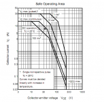
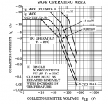
Look up the 25degC SOA for 75V, find what currents can pass reliably for the DC load condition and for the one shot, short terms of 100ms, 10ms and 1ms.
You will find ~800mA for DC, 1.3A for 100ms, 6A for 10ms and 22A for 1ms.
These all have to be de-rated for your expected operational temperature.
You can see that neither a hot, nor a warm 1943 can pass a single shot 2.25Apk for as long as 100ms. It is very likely a warm to medium hot 1943 could reliably pass 2.25Apk for longer than 10ms.
There's the decision the designer has to make. Is one shot capability for longer than 10ms reliable enough?
Test to destruction to find out.
Or maybe play safe and run the amp cooler or add more pairs.
I would recommend 4pair 1943/5200 for domestic duty, run no more than warm, into 8ohm speakers, on +-77Vdc supply rails.
Other may say you can do much more than this.
You weigh up the evidence and you decide.
the output transistor Vce can be from -77Vdc to 154Vdc for the worst case extremes of reactive and resistive loadings assuming no losses through the output stage itself.
When feeding a real resistor load the range of Vce is 0Vce to Rail to Rail (154Vdc).
When current to the load is at maximum the Vce is usually near minimum. Unless you short the output and send maximum input signal.
The worst case for resistive peak power dissipation is when Vce ~ half Rail voltage and output current is ~ half peak current.
This is a condition that will be passed through instantaneously very regularly.
It is very easy to design the output stage to meet this resistive peak dissipation.
When feeding a reactive load where the output voltage is not in step (out of phase) with the output current, there are many situations during complex music cycles that high output current and medium to high Vce can co-exist.
This is a much more difficult condition to design for. Luckily it too is a short term instantaneous peak power through the output device.
As an empirical (rule of thumb) guide for using moderately reactive speakers expect the worst case IV across the output device to occur when output voltage is zero volts and the output current is approximately half of the peak resistive load current. i.e. Vce~=Vrail - zero volts - a couple of volts of losses.
For your +-77Vdc supplies use reactive Vce~72Vdc.
For a 4ohm resistive load the peak output current is 72/4 = 18Apk.
Half this value is 9Apk. if you have 4pair then the Vce=72V and Ireactive =2.25Apk
Look up the 25degC SOA for 75V, find what currents can pass reliably for the DC load condition and for the one shot, short terms of 100ms, 10ms and 1ms.
You will find ~800mA for DC, 1.3A for 100ms, 6A for 10ms and 22A for 1ms.
These all have to be de-rated for your expected operational temperature.
You can see that neither a hot, nor a warm 1943 can pass a single shot 2.25Apk for as long as 100ms. It is very likely a warm to medium hot 1943 could reliably pass 2.25Apk for longer than 10ms.
There's the decision the designer has to make. Is one shot capability for longer than 10ms reliable enough?
Test to destruction to find out.
Or maybe play safe and run the amp cooler or add more pairs.
I would recommend 4pair 1943/5200 for domestic duty, run no more than warm, into 8ohm speakers, on +-77Vdc supply rails.
Other may say you can do much more than this.
You weigh up the evidence and you decide.
Last edited:
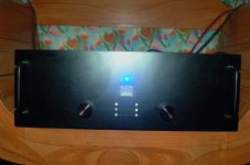
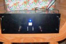
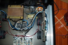
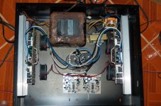
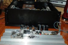
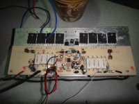
at last mounting is done Ty APEX
next project H900
no bridge switch?
no bridge switch?
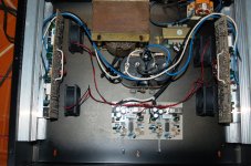
nope no bridge,actually this casing is for the APEX H900 with bridge nimi dip switches and active sub xover this casing is too big for B500.
TY Turbo pro
apex,
i already have two b500 amp,
i struggle to find where,how they have two different output(ac) when input signal fed,of course i would love to have the higher ac(spl) one, or balance same power from my L/R.they share same psu i compare every test point,and found out the weaker one,is having low reading on R20/21, so i change the two 1k to about 680r the reading improve,but the still the output sound is not as louder as the other,
where is the possible fault,where is my test point?
apex,
i already have two b500 amp,
i struggle to find where,how they have two different output(ac) when input signal fed,of course i would love to have the higher ac(spl) one, or balance same power from my L/R.they share same psu i compare every test point,and found out the weaker one,is having low reading on R20/21, so i change the two 1k to about 680r the reading improve,but the still the output sound is not as louder as the other,
where is the possible fault,where is my test point?
Measure DC voltages can't give you information about AC gain, can you post pictures of this two amps...
driver
what do you think is the suitable driver for the amp on this site???
Crown - The Professional Choice
any suggestions..
thanks
what do you think is the suitable driver for the amp on this site???
Crown - The Professional Choice
any suggestions..
thanks
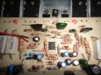
b500 channel b
i'm satisfied with this one
Measure DC voltages can't give you information about AC gain, can you post pictures of this two amps...
i'm satisfied with this one
Attachments
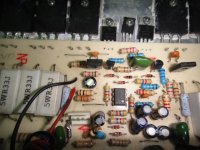
apex a i am not familiar with one component of the B500 amp . That is the nsl32. what is it and can i omit that part with no problem for the amp
NSL32 is optoresistor for limiter funktion, amp can work without NSL32, but you don't have clip limiter.
For AC gain check resistors value:
First stage with AC gain is around ICa: R4(43k)/R1(3k3)+R2(10k),
Second stage with AC gain is around Q1,Q2: R19(22k)/R12(1k),
You probbably use two resistors 33k and 10k in series instead one of 43k for R19,
Regards
43k not available in 5% tolerance .5w
does series affect my gain stage?
soon i will replace this 43k (precision 1% but 1/4w)
- Home
- Amplifiers
- Solid State
- 500W PA amplifier with Limiter