and this is from apex audio
How many watt you get using this method "TEF" ?
Salam kenal
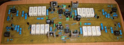
I assemble with 8 pairs toshiba, using 15 A transformer with voltage 2 x 55 Vct. I used to drive speakers faboulus 2 x 18 "4 ohms, the result is very satisfactory, i like itHow many watt you get using this method "TEF" ?
Salam kenal
Greetings also
")
How many watt you get using this method "TEF" ?
Salam kenal
Cool. Thx 4 the info bro
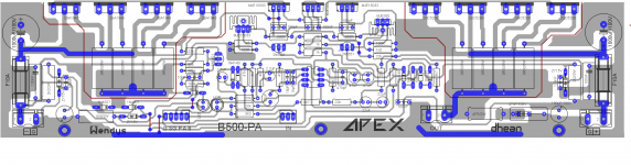
I will make a B500 with a length of 30cm, please in this layout correction if there is a mistake,,,, sorry my bad english. Thank you so much.
Bikin yg pake sanken kang, 8 batang sekalian
No sir MR Vedmitraa, B500 is the only standard length are changed, I happened to have a heatsink 30cm. There is nothing wrong with the layout sir??
thk
77-0-77 VDC absolutely right. scheme while no corresponding change in the scheme Mr. Mile, the final transistor is not too hot, just hot on the driver, but after being given the fan its ok. I wear a speaker protector existing B500 standard fan speed control,55-0-55 A.C. that is around 77-0-77 Volt D.C. if I am correct not 90-0-90 as in layout, Did you have to put a delay start in it, how was the heat of outputs on load,Is there any more changes in component value in your layout.thanks in advance for getting the reply.
regards
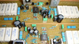
For checking
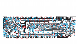
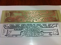
Hello Everyone... Hope it's ok to post it here since this is just a reply to the post above. I manage to merge the parts & PCB layout hoping anyone can checked if its correct. There are some parts which values are not available... hoping also anyone can give suggestion. Anyone else have tried this layout aside from Mr. Liem Poo?
many thanks in advance
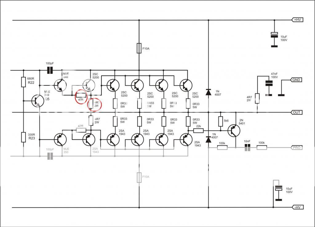
Layout H 900 TEF and B 500 TEF
Hello Everyone... Hope it's ok to post it here since this is just a reply to the post above. I manage to merge the parts & PCB layout hoping anyone can checked if its correct. There are some parts which values are not available... hoping also anyone can give suggestion. Anyone else have tried this layout aside from Mr. Liem Poo?
many thanks in advance
Attachments
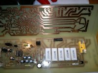
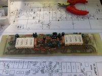
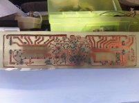
additional pics. my board is a mirror image, so i have to solder the all trans and ic to the copperside.
got few questions. 470pF number code is 471, but electronic sales staff gave me 470. for 33pF number code is 330, but staff gave me 331. i'm doubtful if it is correct. is this correct?
got few questions. 470pF number code is 471, but electronic sales staff gave me 470. for 33pF number code is 330, but staff gave me 331. i'm doubtful if it is correct. is this correct?
Attachments
- Home
- Amplifiers
- Solid State
- 500W PA amplifier with Limiter