If reality worked the way you worded it, everyone would use 100 speakers connected in parallel, powered by a single 1W amp, as opposed to a single speaker ran by a 100W amp. See the discontinuity here?
Unfortunately this does not work because you half your power every time you add a speaker.
That is because all human perception is logarithmic, including non-sensory ones (such as time). Dynamic range compression is a very effective way to map the huge range a perceptible stimulus can take to a limited neural representation, while preserving high differentiating ability in the most important region of that range.10db of gain is generally percieved to be about twice as loud.
Mr Teal said:Though I have no formulas to back it up, the general rule of thumb is that a doubling of total power results in a 3 db increase, and a doubling of cone area results in a 3 db increase.
By definition, 3dB (approximately, actually, but quite close) is double the power, and it even has a convienient equation to go with it. As for cone area, the extra mass and radiation takes more power to drive, at least as many dB. (I don't know much about speaker design, but most larger speakers have more favorable efficiency ratings than smaller speakers, so let's call it -2dB for a total of +1dB for double the area.)
Easyamp said:
Every time you add a speaker you increase your gain by 3db when you add 2 speakers you increase your db by 10,
I'm not just making this up, it's fact.
For every 3db of gain you'll roughly need to double your output power and for 10db of gain roughly 10 times the power.
10db of gain is generally percieved to be about twice as loud. so if I have three speakers each with one hundred watts of power it will be equivalent to one speaker being driven with a 1000 watt's.
Okay. So where does the 700W come from? Out my <moderated by self>?
Tim
Easyamp said:
Unfortunately this does not work because you half your power every time you add a speaker.
(Ohp, third page here...) Okay, so you acknowledge reality works. So where does the halved power come in in your example, and where does the 700W come from?
Tim (snickering)
For such high power SMPS, two stage design is recommanded. A PFC (power factor correction) converter as the first stage which converts AC into DC (~400VDC). The advantage of using PFC converter instead of simply a bridge and capacitor is that it provides high power factor (close to 1) and draws sinusoidal current from the AC source which can greatly reduce the RMS current and surge current at the input. The second stage is a DC to DC converter which converts 400VDC to the desired output DC voltage. To reduce hot spot and heat locallization in the second stage, I think about 5 converters (1000W each) working in parallel with current share control like droop control is better. This reduces the power rating of each component and eases the component sourcing problem. To improve the efficiency of the whole converters, you may try some converter topologies with zero voltage switching like asymmetrical drive half-bridge converter and full bridge converter etc.
Joe Liu
Joe Liu
How I understand speakers is that when you double the number of speakers/drivers connected in parallel, you get a 3dB increase in sensitivity, however with lower impedance. It's still off 1 watt, but it might be 4 ohms nominal rather than 8 (so 2 volts rather than 2.83 with more amps behind it).
If you double the number of speakers/drivers connected in series, you get double the impedance with no effect on sensitivity. Off one watt, you cut the power to each speaker to 0.5 watts (decrease in volume by 3dB) but make up for it by having two speakers (increase in volume by 3dB).
So, a common thing for speaker builders (well, more line array builders) to do is have 4 drivers. Two sets of pairs of drivers will be connected in series (doubling their impedance), then these two pairs of drivers will be connected in parallel (halving their impedance). So this will keep your original impedance and give you a 3dB increase in sensitivity.")
Reece
If you double the number of speakers/drivers connected in series, you get double the impedance with no effect on sensitivity. Off one watt, you cut the power to each speaker to 0.5 watts (decrease in volume by 3dB) but make up for it by having two speakers (increase in volume by 3dB).
So, a common thing for speaker builders (well, more line array builders) to do is have 4 drivers. Two sets of pairs of drivers will be connected in series (doubling their impedance), then these two pairs of drivers will be connected in parallel (halving their impedance). So this will keep your original impedance and give you a 3dB increase in sensitivity.
Reece
I agree with Joe Liu,
you have to build PFC first for such power level. I saw the 3kW PFC unit built with Motorola's MC34262 chip but this looked a bit crazy, choke was of gigantic size - this is 'critical conduction current mode' controller, see its datasheet, primarily designed for under 500W power levels, so it uses variable frequency modulation.
I tried myself STM's L4981A controller and that's what I suggest for power of kilowatts. You can take its basic circuit (found in datasheet), replace main switch for, say, 2 pcs. of IRG4BC40U, calculate its choke, add a bank of 450V capacitors. L4981A chip is also used in some 19" CRT monitors; I repaired hundreds of them, with only 2 or 3 cases of PFC unit itself failed. This says for its durability. You will have total efficiency some decreased (PFC efficiency is usually under 96%), but with caps bank large enough you can have almost 'stabilized' 400V for H-bridge supply.
Then, if I were you, I would make H-bridge with same IRG4BC40U, 4 pcs, take SG3524 as driver and 2 pcs of IR2110 for gate drivers. SG3524 can be synchronized with L4981A for minimum noises, I'd take 80kHz synchro, thus H-bridge frequency of 40kHz. You will also need to add source resistors for minus rail IGBTs to provide overcurrent sensing by SG3524. For feedback I'd take simple zener-npn-optocoupler back to SG3524.
Transformer design is very critical. I made myself up to 1kW and that was some diffcult in terms of efficiency. You need to learn much about proper winding One more thing is voltage*second area of transformer operation: in half-bridge you easily make it equal by cap divider; in full-bridge you probably need to put in series with primary winding some high-voltage film capacitors. My calculation shows the need for about 10uF. In one 1kW design I saw serial LC-network (also with big choke) for normalized switching; but it's not the easy case to begin with.
And, be careful with p.c. board layout.
Good luck, we're waiting for your reports
Alex.
you have to build PFC first for such power level. I saw the 3kW PFC unit built with Motorola's MC34262 chip but this looked a bit crazy, choke was of gigantic size - this is 'critical conduction current mode' controller, see its datasheet, primarily designed for under 500W power levels, so it uses variable frequency modulation.
I tried myself STM's L4981A controller and that's what I suggest for power of kilowatts. You can take its basic circuit (found in datasheet), replace main switch for, say, 2 pcs. of IRG4BC40U, calculate its choke, add a bank of 450V capacitors. L4981A chip is also used in some 19" CRT monitors; I repaired hundreds of them, with only 2 or 3 cases of PFC unit itself failed. This says for its durability. You will have total efficiency some decreased (PFC efficiency is usually under 96%), but with caps bank large enough you can have almost 'stabilized' 400V for H-bridge supply.
Then, if I were you, I would make H-bridge with same IRG4BC40U, 4 pcs, take SG3524 as driver and 2 pcs of IR2110 for gate drivers. SG3524 can be synchronized with L4981A for minimum noises, I'd take 80kHz synchro, thus H-bridge frequency of 40kHz. You will also need to add source resistors for minus rail IGBTs to provide overcurrent sensing by SG3524. For feedback I'd take simple zener-npn-optocoupler back to SG3524.
Transformer design is very critical. I made myself up to 1kW and that was some diffcult in terms of efficiency. You need to learn much about proper winding
One more thing is voltage*second area of transformer operation: in half-bridge you easily make it equal by cap divider; in full-bridge you probably need to put in series with primary winding some high-voltage film capacitors. My calculation shows the need for about 10uF. In one 1kW design I saw serial LC-network (also with big choke) for normalized switching; but it's not the easy case to begin with.And, be careful with p.c. board layout.
Good luck, we're waiting for your reports
Alex.
I'm sorry you thought of it as a side track, I was only trying to help you achieve your goals but with maybe less work. If interested this page has interesting numbers on it, but he only uses one power source so it doesn't show what I was talking about.
http://www.audioasylum.com/audio/speakers/messages/185515.html
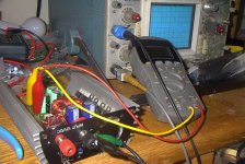
I'm all for high power it just seems easier to build a few smaller psu's like the one pictured below and just increase the effenciey off your speaker system so to achive the same in the end with less work and money. Makes sense to me?
If interested in the supply it's 40v+/- with short and thermal protecion tested to 700watts.
http://www.audioasylum.com/audio/speakers/messages/185515.html
I'm all for high power it just seems easier to build a few smaller psu's like the one pictured below and just increase the effenciey off your speaker system so to achive the same in the end with less work and money. Makes sense to me?
If interested in the supply it's 40v+/- with short and thermal protecion tested to 700watts.
Attachments
Just had a chat with our power supply guy about "how do you make a 5KW PSU for audio?"... he did it before in a previous job, but with 4KW of output.
He didn't use PFC, he used rectified 3-phase AC which gave a decent power factor. He used a phase-shift controller (ML4148) driving a mixture of MOSFETs and IGBTs - MOSFETs for leading switchines, IGBTs for lagging. Switching frequency was 75KHz. The transformer was made using a pair of ETD49 cores, and a beefy series capacitor was used on the primary winding to compensate for leakage inductance.
The output was synchronously rectified using MOSFETs, driven from extra windings on the main transformer. This allowed reverse current to flow in the output inductors, which helped with stability under light loading. Output inductors were a pair of ETD49s.
It was forced air cooled, and it and an audio amp both fit inside a 2U rackmount enclosure.
The guy tells me he that he shouldn't disclose who made the amp, and he certainly won't if i'm gonna post it on an internet forum.
hello Tekko,
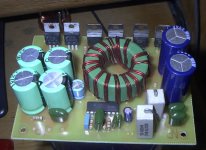
The case is from an inverter, it was a Coleman 500w model.
I'm currently not selling any because I don' know about safety or liabillty issues related to selling things like this.
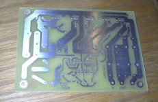
Here a shot of the baord. Thermal and short protection on this project are done off the main board although my schem has it on baord.
The case is from an inverter, it was a Coleman 500w model.
I'm currently not selling any because I don' know about safety or liabillty issues related to selling things like this.
Here a shot of the baord. Thermal and short protection on this project are done off the main board although my schem has it on baord.
Attachments
gmarsh, I know some schematic with mixed FET and IGBT switches, but there are used old 'slow' IGBT types which have long current tail after off gate signal, so both types are turned on at the same moment but IGBTs are turned off 2-3 microseconds before FETs turned off. With modern IGBT series like WARP from IR, life becomes much easier
I also thought that if secondary is +/-63V, then it's maybe really good idea to make 5 power transformers, 1kW each, with turns ratio about one! (assuming connecting primaries in series) This will give the best magnetic coupling and therefore efficiency.
That's also interesting issue about choke reverse current in synchronous rectifier... Although maybe not an easy way to realize, I didn't try myself yet. I tried to calculate: for such a 'high' voltage, we need 200V FETs, then voltage drop is about 1,2V at 60A current (4 pcs of IRFP260 in parallel, high die temperature)... hmm, comes to be ineffective and too expensive yet. Good diode has below 1V drop when heated. Maybe they used combination of low-volt FET and a diode, but this is even more complicated
Alme said:That's also interesting issue about choke reverse current in synchronous rectifier... Although maybe not an easy way to realize, I didn't try myself yet. I tried to calculate: for such a 'high' voltage, we need 200V FETs, then voltage drop is about 1,2V at 60A current (4 pcs of IRFP260 in parallel, high die temperature)... hmm, comes to be ineffective and too expensive yet. Good diode has below 1V drop when heated. Maybe they used combination of low-volt FET and a diode, but this is even more complicated
No diodes!
At high current operation when the inductor current is always positive, the MOSFETs act like diodes. Their body diode handles the great majority of the current, though having the FET switched on will reduce the forward voltage by some measurable-but-not-significant amount.
When inductor current goes negative, the FETs act like resistors instead of diodes. But this only happens at low output currents, so the FETs certainly aren't conducting a full 60A through their Rds(on).
Emmy, I just noticed that you would like to have full power from wide range 90-270VAC input. I remember my first 300W PFC, it was giving out its fair 400VDC at light load with input voltage as low as 30VAC ! that was amazing. I mean this is one more reason to try PFC topology - it will squeeze from any low AC mains
the needed power
gmarsh, thanks for explanation about FET rectifier ! Now I see my mistake - completely forgot about FET body diodes. So synchronous rectifier looks attractive to me now. I definitely need to try it myself
the needed power
gmarsh, thanks for explanation about FET rectifier ! Now I see my mistake - completely forgot about FET body diodes. So synchronous rectifier looks attractive to me now. I definitely need to try it myself
300W PFC
Alme-
Do you have pics of your PFC? I made onw a few years ago for me senior project, and got an "A" on it. Good thing the Professor didn't ask me to plug it in- When I did (at home) the 5A fuse blew right away!
I never tried it again, and I would post a pic or two of it here, but even at the lowest resolution setting , the JPEGs are still too big for posting here (>100K).
I am curious: what PFC chip did you use? what kind of core material for the inductor did you choose? Number of turns? MOSFET used? As you probably know, we have only 120VAC here in the States (OK, it's really 120/240V Split-phase, but almost ALL outlets here are wired for 120V ), but I am interested in making a PCF (>500W) for a few SMPSs I have laying around, and I want it to be worldwide compatible. Thank You.
Steve
Alme-
Do you have pics of your PFC? I made onw a few years ago for me senior project, and got an "A" on it. Good thing the Professor didn't ask me to plug it in- When I did (at home) the 5A fuse blew right away!
I never tried it again, and I would post a pic or two of it here, but even at the lowest resolution setting , the JPEGs are still too big for posting here (>100K).
I am curious: what PFC chip did you use? what kind of core material for the inductor did you choose? Number of turns? MOSFET used? As you probably know, we have only 120VAC here in the States (OK, it's really 120/240V Split-phase, but almost ALL outlets here are wired for 120V
), but I am interested in making a PCF (>500W) for a few SMPSs I have laying around, and I want it to be worldwide compatible. Thank You.Steve
Hi, Steve,
unfortunately I don't have any pictures of that PFC, and cannot take them, because it was made 2 years ago at home and now I live very far from home. But I remember some details. I used components by STM: PFC chip L4981A, and schematic taken from its datasheet. I was very satisfied with its operation which is generally the rare case Operation frequency of 100kHz; later I tried to synchronize it with other chips in power supply system: UC3842 and TL494 - everything worked well. Power switch was STW12NA60, actually that was the only reason why I didn't take more than 300W out of device: this MOSFET heats more at higher than this load, which my heatsink didn't allow. For power over 500W you better try IRFP460 or new generation IGBT like IRG4BC40W. Flyback diode was 5A type of STM' turboswitch series (don't remember its index). Inductor was tried on two different cores - EE type and pot type, both about 50mm size, usual ferrite with mu=2000, gapped with plastic card pieces I adjusted gap to get inductance of 4mH with about 160 turns of wire. Both chokes worked well, remaining just warm under load. Output capacitor was bank of 700uF/450V. That's it.
Steve do you think it's right time to start a new thread here named 'PFC discussion' ?
Regards,
Alex.
unfortunately I don't have any pictures of that PFC, and cannot take them, because it was made 2 years ago at home and now I live very far from home. But I remember some details. I used components by STM: PFC chip L4981A, and schematic taken from its datasheet. I was very satisfied with its operation which is generally the rare case
Operation frequency of 100kHz; later I tried to synchronize it with other chips in power supply system: UC3842 and TL494 - everything worked well. Power switch was STW12NA60, actually that was the only reason why I didn't take more than 300W out of device: this MOSFET heats more at higher than this load, which my heatsink didn't allow. For power over 500W you better try IRFP460 or new generation IGBT like IRG4BC40W. Flyback diode was 5A type of STM' turboswitch series (don't remember its index). Inductor was tried on two different cores - EE type and pot type, both about 50mm size, usual ferrite with mu=2000, gapped with plastic card pieces I adjusted gap to get inductance of 4mH with about 160 turns of wire. Both chokes worked well, remaining just warm under load. Output capacitor was bank of 700uF/450V. That's it.Steve do you think it's right time to start a new thread here named 'PFC discussion' ?
Regards,
Alex.

- Status
- This old topic is closed. If you want to reopen this topic, contact a moderator using the "Report Post" button.
- Home
- Amplifiers
- Power Supplies
- 5000w Smpsu!