I'll use the 10K pots that I have.
Ordered the STP CAT6 from Monoprice to replace my current UTP and get rid of the hiss and hum.
Question tho; is using CAT6 UTP for 20 to 30 foot surround speaker leads a good or bad idea? The combination of all eight 24 awg sums up to a 15 awg wire.
Ordered the STP CAT6 from Monoprice to replace my current UTP and get rid of the hiss and hum.
Question tho; is using CAT6 UTP for 20 to 30 foot surround speaker leads a good or bad idea? The combination of all eight 24 awg sums up to a 15 awg wire.
put the distant power amps at the speakers.is using CAT6 UTP for 20 to 30 foot surround speaker leads a good or bad idea? The combination of all eight 24 awg sums up to a 15 awg wire.
Then your CAT5/6 pair only has to carry line level signals.
I thought of that. Make the amps as compact as possible and incorporate them into the speaker cabinet.... However, next issue would be to install AC outlets specifically for them since there are none close by. The other issue (which I was alluding to) is cost. Just can't do it right now. Will consider in the future as HT upgrades.
Okaaaaaay.. Even with the shielded CAT6 still getting some racket. Funny tho, my first test was night and day.. now no change. Noise!
 and
and 
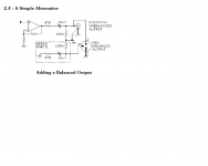
So, since the DCX2496 is balanced I will add a balanced circuit in the amp. I'll obviously need 3 (3 ch amp). I've quickly gone through this site about balanced entry to amp but unsure about what I truly require.
Andrew I noticed on a separate post/reply about only needing an Input Transformer with 3 passive Components but mentioned "quasi balanced" results? Or do I need to get into a more elaborate circuit like a Burr Brown DRV134 DIY BPA300 6x LM3886 300W audio Amplifier
and So, since the DCX2496 is balanced I will add a balanced circuit in the amp. I'll obviously need 3 (3 ch amp). I've quickly gone through this site about balanced entry to amp but unsure about what I truly require.
Andrew I noticed on a separate post/reply about only needing an Input Transformer with 3 passive Components but mentioned "quasi balanced" results? Or do I need to get into a more elaborate circuit like a Burr Brown DRV134 DIY BPA300 6x LM3886 300W audio Amplifier
you can convert the DCX2496 from balanced output to unbalanced output by two simple almost no cost methods.
Short the Cold Pin to the Ground Pin in the receive end of the cable. Label this plug appropriately.
or
connect a dummy load resistor from Cold Pin to Ground Pin.
The Hot Pin voltage will change when you swap between the two methods, although when I tried it the Hot voltage did not change. I never investigated why it didn't.
The dummy load resistor could match the Rin of your amplifier/receiver.
You can convert any unbalanced output to a quasi balanced (impedance) output that can feed any balanced input. The "Quasi" part is due to all the signal appearing on the Hot Pin and zero volts signal appearing on the Cold Pin. Balanced inputs don't care where the voltages come from, they read the difference in voltage and amplify that difference.
Go to Jensen (or maybe it was Rane) and find the app note that describes the various balanced and unbalanced connection options. Copy the quasi balanced. It needs two resistors and one capacitor.
Last edited:
are you confirming that the added shield around the twisted pair gave no improvement, or insufficient improvement?Okaaaaaay.. Even with the shielded CAT6 still getting some racket.
I use quite long lengths of twisted pair and I get no interference.
Quote:
Originally Posted by benlalonde
Okaaaaaay.. Even with the shielded CAT6 still getting some racket.
are you confirming that the added shield around the twisted pair gave no improvement, or insufficient improvement?
I use quite long lengths of twisted pair and I get no interference.
__________________
regards Andrew T.
The scenario is this: As soon as I plug in the first UTP CAT cable into the input stage, noise and lots of it. That's with the other end unplugged from the driver (DCX2496). But when I plug into the driver the noise slightly reduced (as long as the driver is switched on).
Test with STP CAT cable: Same as above; unplugged from the driver and plugged into receiver gives me same noise. HOWEVER, when I first tried this I connected the exposed shield on the receiver end with alligator clipped wire to the Audio Ground. The noise was tremendously reduced (no hum) ..but still had a small amount of hiss coming from the midrange and tweeter. It was low enough to be acceptable.
Now when I go through the same exercise, no change to the ever present hum and hiss. Still as loud as it was before testing with the STP cable.
I've also tried grounding the shield at the driver end to either Pin 2 and Pin 3 (with signal ground) ..no change. Now I know for a fact the hum is ground looping back into the signal. The hiss I'm not sure if this is airborn noise being picked up by the CAT cable or a higher pitch of the ground hum.
Earth Hum at 60 Hz
Is it possible for an unbalanced amplifier to "over" amplify earth hum from 60hz to 200hz in form of 2nd and 3rd harmonic peeks in the bass section of loudspeakers?
Reason for my query is that I'm measuring a very substantial increase of DB from 60 to 200Hz when doing a frequency response. I am baffled as to what is causing this. Could it be the amp or bass driver and bass cabinet??
Last edited:
60 Hz mains lead to 120 Hz buzz after rectification. An increase in a frequency range sounds more like a misaligned bass cabinet or room interaction. Move the box to a different place and check whether the situation changes. A misaligned speaker would mean a closed box is too small or in the case of a bass-reflex box it is either too small or the tuning frequency is too high or both.
Hi,
I'm not too good with this AC stuff.
But I recall a passive filter type that instead of rolling off from flat to -3dB when phase is at 45degrees and then continuing to fall at ~-6dB/octave, rises from flat to +1 to +3dB and then rolls off more abruptly to hit the F-3dB to continue at the -6dB rate.
Is this when two single pole Butterworth RC are cascaded?
BTW it also occurs at the HF roll off as well.
But I recall a passive filter type that instead of rolling off from flat to -3dB when phase is at 45degrees and then continuing to fall at ~-6dB/octave, rises from flat to +1 to +3dB and then rolls off more abruptly to hit the F-3dB to continue at the -6dB rate.
That's a fairly high-Q response only possible in passive form if inductors are employed. RC can't give such high Q. Alternatively its easy to get with a Sallen-Key lowpass arrangement around an opamp - give it more feedback (increase the feedback cap) and the Q goes up.
60 Hz mains lead to 120 Hz buzz after rectification. An increase in a frequency range sounds more like a misaligned bass cabinet or room interaction. Move the box to a different place and check whether the situation changes. A misaligned speaker would mean a closed box is too small or in the case of a bass-reflex box it is either too small or the tuning frequency is too high or both.
I think I finally found the problem to the high bump. It's not an amplification or RF noise issue as you suggested. It's my fabrication method of the cab. I CNC machined an elliptical layered enclosure out of 1" MDF. The rear of the cab is decent however the front baffle is weak. Since the orientation is 90º to the front baffle AND the driver cut-out is an 1" deep, results in extreme resonance rise from 100 to 200 Hz. I mean bad! The driver has very little to vent properly and therefore focusing all that acoustic energy on an already weak baffle. So, I'll have to reface the cab front baffle and replace it with either a 3/8" aluminum plate or 3/4" MDF board. But this time I'll oversize the cut-outs a bit and add a generous chamfer on the inside. That should ease the peek I'm getting.
- Status
- This old topic is closed. If you want to reopen this topic, contact a moderator using the "Report Post" button.
- Home
- Amplifiers
- Chip Amps
- 5.1 Channel Chip Amp/Gainclone for Home Theater