otto88 said:I’m only interested if I know that KT90s work well in UL mode too . .
Cheers
I did some tests a couple of years back....expect roughly double the thd (at 1Khz) from KT90's when put in a fixed bias p-p UL KT88 circuit. Unless for MI apps, there's absolutely no point for doing this for Hifi.
richj
Eli Duttman said:Power drive DC couples the FET to the "final". I suggest you DC couple the FET to the splitter. The requisite individual bias adjustments for PPP make (IMO) a single FET and individual coupling caps. more attractive than a single coupling cap. and multiple FETs.
Say we have a KT88 tube's grid after the 1uF cap and there is the -45V Bias for it. The current drive will be strong so to use more KT88s, and an IRF610 has only 15pF Crss without being a difficult to get part. No need for negative PSU. All well, but we still get blocking distortion if we drive hard and not DC couple to grid a' la Powerdrive, don't we?
*Thread resurrection.
")
Attachments
Salas,
Any time a cap. is in the g1 circuit, the possibility of blocking distortion is present. IIRC, you are talking about 4X KT88s/Channel wired PPP. You would need an individual FET driver for each "final" to prevent blocking distortion and allow for individual "idle" current set. Such an arrangement has definite plusses. While I would not go deeply, KT88s can work well in a positive g1 current regime. Individual DC coupled driver FETs can take you there.
Asking a 3 mA. 12AT7/ECC81 section to drive the reverse transfer capacitance of 2X power MOSFETs might be asking for trouble. Yet more "sand" can guarantee things will work well. DC couple ZVN0545A source followers to the 'T7 anodes. Cap. couple the little FETs to the power FET drivers.
Any time a cap. is in the g1 circuit, the possibility of blocking distortion is present. IIRC, you are talking about 4X KT88s/Channel wired PPP. You would need an individual FET driver for each "final" to prevent blocking distortion and allow for individual "idle" current set. Such an arrangement has definite plusses. While I would not go deeply, KT88s can work well in a positive g1 current regime. Individual DC coupled driver FETs can take you there.
Asking a 3 mA. 12AT7/ECC81 section to drive the reverse transfer capacitance of 2X power MOSFETs might be asking for trouble. Yet more "sand" can guarantee things will work well.
DC couple ZVN0545A source followers to the 'T7 anodes. Cap. couple the little FETs to the power FET drivers.I'm in the pencil and paper stage of the design of a PPP KT88 amp at the moment. I'm using VDV2100 CFB/H Toroidal Output trannies and Mennos's "Supertriode" (Ultralinear + cathode feedback) arrangement - and Gold Lion Re-issue KT88
Based upon experience with my comparatively tiny Baby Huey I will be using individual Current Source loaded MOSFET Source Followers direct coupled to each output tube.
The baby Huey experience:
Even with Ultralinear connected EL84 I found significant improvements when I
1) Used a MOSFET (ZVN545A) source follower direct coupled to the outputs.
2) A further improvement when I increased the source follower current from 0.5mA to 2 mA. I swear I could hear the amp give a sigh of relief when I made this change. It became much more relaxed and music sounded "effortless".
3) A further improvement again when I changed to a current source load on the source followers. That current source was a simple ring of two transistor CCS. I measured its impedance at only 135K but it improved the sound significantly over the 33K resistor I had previously used as the load.
The Source Followers were AC coupled to the front end with small caps (taking advantage of the large input impedance to the source followers) and Fixed bias was applied to the MOSFET gates.
I will be using this scheme in my PPP KT888 with 2 new "wrinkles":
1) Im going to bootstrap the Source follower supply using a BJT Darlington - this addresses Crss issues.
2) Im providing the bias to the gates via bias servos to guarantee idle current balance in the toroidal output tranny.
For KT88 in Triode Mode:
To properly drive a KT88 in triode mode I would be aiming for (looks behind himself to check where the value came from) at least 8 to 10 mA in the follower.
Other (maybe relevant) experience:
I am fixing a friends JADIS JA80 Monoblocks right now. These are Ultralinear PPP KT88 with POSITIVE Cathode Feedback and some shunt negative feedback from the KT88 anodes back to the driver which in the unique JADIS style is a wimpy 12AX7. When looking at these amps output on an Oscilloscope the slew rate limiting stands out like the proverbial canine testicles.
Just one mans experience and views - feel free to disagree.
Cheers,
Ian
richwalters said:
I did some tests a couple of years back....expect roughly double the thd (at 1Khz) from KT90's when put in a fixed bias p-p UL KT88 circuit. Unless for MI apps, there's absolutely no point for doing this for Hifi.
richj
hey-Hey!!!,
I have Type 3 KT90 running in heathkit W6m chassis. They do( without grid current ) 60W at less than 5%, and by the residual, there's little high-order. They're not open loop, and they're running the 40% U-L tapping the 16431 OPT provides( and 2k8 a-a load to 8R ). That is the same THD performance I got later with 6550A and T-S 6550.
To the OP-er, I'd use cascode, depletion-mode MOSFET's for the followers *AND* run them direct coupled to the finals. Getting away from single FET implementations here is likely even more important in this circuit v. use in LTP phase splitters...capacitance stabilization and reduction( end-to-end ) is quite valuable. A 5687 plate can easily drive the 'grid' resistors of the multiple gates.
cheers,
Douglas
Bandersnatch said:
I have Type 3 KT90 running in heathkit W6m chassis. They do( without grid current ) 60W at less than 5%, and by the residual, there's little high-order. They're not open loop, and they're running the 40% U-L tapping the 16431 OPT provides( and 2k8 a-a load to 8R ). That is the same THD performance I got later with 6550A and T-S 6550.
The problem is analogue thd analysers don't show the whole picture. I found the KT90 harmonics cluttered and untidy (as expected for sweep tubes) in the odd order when compared to the 6550 group. Unfortunately I don't have any more KT90's around.
If your 5% thd doesn't signifigantly change when changing o/p stage tubes from KT90 to 6550, then high thd is originating elsewhere.
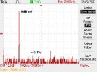
A well designed 6550 parallel p-p AB amp using good quality o/p trannies for HiFi should obtain a sim spectrum as in pic. In each case I found the performance of the 6550 group very close to KT88 in same socket. Beware 6550; KT88, B+ limits aren't same .
0dB = 100W; the 3rd harmonic is under 0.1%.
The GEC 400W shown in post 5; sometime ago I tried this and found not a good performer. With 4 o/p tubes and conventional diff driver offered better results.
richy
Attachments
gingertube said:Based upon experience with my comparatively tiny Baby Huey I will be using individual Current Source loaded MOSFET Source Followers direct coupled to each output tube.
2) A further improvement when I increased the source follower current from 0.5mA to 2 mA. I swear I could hear the amp give a sigh of relief when I made this change. It became much more relaxed and music sounded "effortless".
3) A further improvement again when I changed to a current source load on the source followers. That current source was a simple ring of two transistor CCS. I measured its impedance at only 135K but it improved the sound significantly over the 33K resistor I had previously used as the load.
I will be using this scheme in my PPP KT888 with 2 new "wrinkles":
1) Im going to bootstrap the Source follower supply using a BJT Darlington - this addresses Crss issues.
For KT88 in Triode Mode:
To properly drive a KT88 in triode mode I would be aiming for (looks behind himself to check where the value came from) at least 8 to 10 mA in the follower.
Just one mans experience and views - feel free to disagree.
Cheers,
Ian
Thanks for your input guys.
Ian:
I was thinking about using 10mA depletion mode CCS under each source follower. Don't know why I thought of that number too.
About the Crss issue, I wonder, if I use say an IRF840 with 250V across it, looking at its capacitance spec I see a low, almost flat region that still accommodates 50V swing towards 200V. Can this guard against phase distortion enough so to make a silk purse from a sow's ear, and not complicate the issue? I have enough of them in my stash.
I have a 320V centrally tapped transformer. Will a simple RC filtered symmetric supply be enough in quality for the buffer stage, given the use of CCS and no gain?
Attached, a rough guide of the idea.
Attachments
otto88 said:Is EI still in production?
Originally posted by AR2 I do not know for sure. I know that they have changed the ownership and that people that used to do it started it on their own or they were planning to start it on their own
As I know, the EI has stopped it's production in 2006 and don't come back business again.
Last news was that Westrex Inc. (Western Electric) was bought EI's production equipments and toolings, and that they has planned to move the factory from Serbia to US of A.
Chattanooga area in Tennessee was mentioned...
Salas,
In the BH I took the approach you suggest with regards to Crss. If you choose the drain supply voltage such that at max positive signal swing at the source you still maintain say 25 Volts minumun VDS then Crss should not vary with signal swing. Bootstrapping the drain just means that there is no signal swing across Crss.
Cheers,
Ian
Thanks Ian. I will do that then. Sheldon on a nearby thread mentioned that after experiencing some intermittent oscillation with his CCS under the SF FET, used 10K resistors, and could not detect a subjective difference. Quite contradictory to your finding. Can there be an explanation maybe when the CF current is set high enough?
P.S. You did not tell me if the SF symmetric supply needed is a tight issue for quality. A reg makes a big difference? Or RC filtering will do for the most part?
P.S. You did not tell me if the SF symmetric supply needed is a tight issue for quality. A reg makes a big difference? Or RC filtering will do for the most part?
Salas,
If he experienced oscillation in the source follower I would be looking at the gate stopper resistor. Usually you can get away with something as low as 33 Ohms BUT I routinely use 220 Ohms and would not be surprised to find that in some situations a higher value may be required.
I've seen a few circuits using MOSFETs posted here (and elsewhere) where no gate stopper was used - that is just asking for trouble.
If the oscillation was in the CCS then cure would depend upon the CCS used - with the simple ring of two a 100 Ohms in the top transistor base should fix it.
I found that the Drain Supply bypassing was critical for sound. I originally used a 40uF electrolytic. Changing to a 10uF polyprop. took a harsh edge of the top end.
When ever you use a cathode, emitter or source follower you need to consider that the input is referred not to 0V but to the +ve rail, that is it is referred to the AC 0V presented by the positive rail. That AC 0V is a good as the bypass cap used or if using a regulator it is as good as the output impedance of the regulator - also need to make sure that good regulator output impedance is maintained to way above the audio frequency band.
Cheers,
Ian
gingertube said:Salas,
If he experienced oscillation in the source follower I would be looking at the gate stopper resistor. Usually you can get away with something as low as 33 Ohms BUT I routinely use 220 Ohms and would not be surprised to find that in some situations a higher value may be required.
I've seen a few circuits using MOSFETs posted here (and elsewhere) where no gate stopper was used - that is just asking for trouble.
Cheers,
Ian
I was using 470R and tried 1k. I'm not sure what the problem was, but since I couldn't hear any obvious difference, I decided to quit messing with it and listen to it instead. Someday, I'll get the bug to sort it out. Maybe a regular CCS instead of the IX or DN chip.
Interesting alternative PP driver: http://ppdriver.blogspot.com/
Sheldon
Sheldon said:Maybe a regular CCS instead of the IX or DN chip.
Sheldon
Maybe an MJE ring of two. Or a cascode.
Sheldon said:
I was using 470R and tried 1k. I'm not sure what the problem was, but since I couldn't hear any obvious difference, I decided to quit messing with it and listen to it instead. Someday, I'll get the bug to sort it out. Maybe a regular CCS instead of the IX or DN chip.
Interesting alternative PP driver: http://ppdriver.blogspot.com/
Sheldon
Darius tried to get a discussion going on Audiokarma concerning this circuit but it didn't go anywhere. I was interested but unable to comment due to lack of practical knowledge on the subject
athos56 said:Darius tried to get a discussion going on Audiokarma concerning this circuit but it didn't go anywhere. I was interested but unable to comment due to lack of practical knowledge on the subject
I think a lot of people don't understand his stuff, nor appreciate his communication style. But it can be worth the effort, as he has some pretty interesting stuff. It took me a while to understand his take on Loftin White amps, but once the light came on, I appreciated the spare elegance of the design. I don't really understand this one yet.
Sheldon
This will be my next try:
Sajti
An externally hosted image should be here but it was not working when we last tested it.
Sajti
- Status
- This old topic is closed. If you want to reopen this topic, contact a moderator using the "Report Post" button.
- Home
- Amplifiers
- Tubes / Valves
- 4XKT88 drive