Hi there
I am a peniless musician (bankrupted by a build of the F5 Turbo) who's looking at cobbling together a small tube amp for practice and recording from leftover, scrap and local resources. And I've never built a tube amp before, so go easy on me")
The speaker cab is made from scrap MDF and pine blockboard, and will have two $5 8" fullrange units, nothing worth talking about - very fat tone but low sensitivity. I shall finish the cabs for now and run it off this amp temporarily: 6moons audio reviews: Synergy Hifi 6F3
In my tests, the amp works well enough for its diminutive size, but the speakers are hardly distressed by the power, and the transformers saturate very early specially when hitting the last two strings. It sounds flatulent, and not nearly loud enough. Specially when playing acoustic guitar through it.
I do know I could use different speakers, but you don't really get instrument speakers easily/cheaply in India. I have 4/5 of these tubes in hand (apart from the ones in the amp above) and I was hoping to rustle them together into a little 15-20W amp that I could add into the cab at a later point in time.
So essentially I was thinking of 4 6f3 tubes in PPP config, switchable between triode and UL and a practice setting that would turn off the B+ on one output pentode pair. The triode sections would be used for preamplification, crunch channel and phase splitter duties. My design bible is the book 'Designing V-T amplifiers' by Charles Couch. The configuration is proposed to be flexible, where the amp output could be routed to an external cab, and the speaker be used just by itself if I wanted.
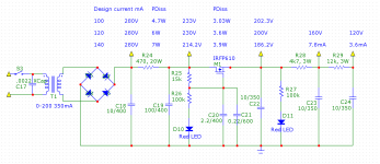
For power, I have a transformer with a single 200V, B+ winding and a couple of 12V heater windings, plus a smaller 12V service winding for use on relays and stuff like that. And a small 40V winding in case I opted for fixed bias. Basically series heaters, and a cap multiplier for the B+. Target B+ is around 250V.
The issue is the output transformer, and this affects pretty much the whole build. I have a custom-wound 13V, 60VA transformer with a UL-tapped primary. This is actually a mains toroid, which is the issue. Given that DC balance is practically mandatory, I was thinking of using a CCS in the cathode using a LM317 or 78xx, one per parallel pair of tubes or even one per tube. This forces Class A operation and somewhat limits the achievable output power, even in pentode mode. At 250V B+ I am seeing about 25mA per tube to stay under the 7W dissipation limit.
I also have a pair of 18V, 18VA EI units, which I could use with parallel secondaries and series primaries but am not sure how this works out in practice. The EIs have much lower bandwidth, I tried both on the output of a standard solid state amp and definitely prefer the toroid. Also the EIs are much smaller, I'm not confident they can take the kind of power required here.
Nobody in our country knows how to wind an OPT, far as I can tell. There are some manufacturers but the less spoken about their units the better. The quality of laminations is very doubtful and the wire is mostly aluminum or iron, not copper. You can forget about split bobbins and interleaved windings, and almost all EIs are so badly put together that they will toast themselves with zero load.
The toroid manufacturers use better materials, and follow specifications quite closely. EI manufacturers tend to be just people with winding machines and not much of a clue. This is the main reason I opted for toroids. I have been following the Van Der Veen publications, at least what is in public domain, to understand the compromises involved in using toroids as OPTs. Shipping in units from overseas is not for peniless musicians like me
Be glad for any advice and assistance, thanks in advance!
I am a peniless musician (bankrupted by a build of the F5 Turbo) who's looking at cobbling together a small tube amp for practice and recording from leftover, scrap and local resources. And I've never built a tube amp before, so go easy on me
The speaker cab is made from scrap MDF and pine blockboard, and will have two $5 8" fullrange units, nothing worth talking about - very fat tone but low sensitivity. I shall finish the cabs for now and run it off this amp temporarily: 6moons audio reviews: Synergy Hifi 6F3
In my tests, the amp works well enough for its diminutive size, but the speakers are hardly distressed by the power, and the transformers saturate very early specially when hitting the last two strings. It sounds flatulent, and not nearly loud enough. Specially when playing acoustic guitar through it.
I do know I could use different speakers, but you don't really get instrument speakers easily/cheaply in India. I have 4/5 of these tubes in hand (apart from the ones in the amp above) and I was hoping to rustle them together into a little 15-20W amp that I could add into the cab at a later point in time.
So essentially I was thinking of 4 6f3 tubes in PPP config, switchable between triode and UL and a practice setting that would turn off the B+ on one output pentode pair. The triode sections would be used for preamplification, crunch channel and phase splitter duties. My design bible is the book 'Designing V-T amplifiers' by Charles Couch. The configuration is proposed to be flexible, where the amp output could be routed to an external cab, and the speaker be used just by itself if I wanted.
For power, I have a transformer with a single 200V, B+ winding and a couple of 12V heater windings, plus a smaller 12V service winding for use on relays and stuff like that. And a small 40V winding in case I opted for fixed bias. Basically series heaters, and a cap multiplier for the B+. Target B+ is around 250V.
The issue is the output transformer, and this affects pretty much the whole build. I have a custom-wound 13V, 60VA transformer with a UL-tapped primary. This is actually a mains toroid, which is the issue. Given that DC balance is practically mandatory, I was thinking of using a CCS in the cathode using a LM317 or 78xx, one per parallel pair of tubes or even one per tube. This forces Class A operation and somewhat limits the achievable output power, even in pentode mode. At 250V B+ I am seeing about 25mA per tube to stay under the 7W dissipation limit.
I also have a pair of 18V, 18VA EI units, which I could use with parallel secondaries and series primaries but am not sure how this works out in practice. The EIs have much lower bandwidth, I tried both on the output of a standard solid state amp and definitely prefer the toroid. Also the EIs are much smaller, I'm not confident they can take the kind of power required here.
Nobody in our country knows how to wind an OPT, far as I can tell. There are some manufacturers but the less spoken about their units the better. The quality of laminations is very doubtful and the wire is mostly aluminum or iron, not copper. You can forget about split bobbins and interleaved windings, and almost all EIs are so badly put together that they will toast themselves with zero load.
The toroid manufacturers use better materials, and follow specifications quite closely. EI manufacturers tend to be just people with winding machines and not much of a clue. This is the main reason I opted for toroids. I have been following the Van Der Veen publications, at least what is in public domain, to understand the compromises involved in using toroids as OPTs. Shipping in units from overseas is not for peniless musicians like me
Be glad for any advice and assistance, thanks in advance!
I assume you are think of this circuit with the output stage "doubled up".
DIY Audio Projects Forum • ECL85 (6F5P ) oddwatt clone
6GV8 = ECL85 Try searching on each to see what else turns up.
The pentode section of the 6GV8 was intended for use in television sets as the vertical amplifier - that means it should be very linear and hence be good for audio output.
For "inspiration" you might like to search for amplifier circuits using other TV vertical amplifier tubes, 6BQ6 comes to mind.
Cheers,
Ian
Cheers,
Ian
@gingertube, I had seen that circuit but I was thinking of using a separate CCS for each tube. The problem is that the toroid will saturate with as little as 3-4mA imbalance between windings and though the balance pot can sort that out at one operating point it cannot compensate for differences in dynamic characteristics of tubes. I am given to understand that modern tubes can have very wide variances because of poorer quality control.
I did search, and there is a lovely circuit and build of a PP 6GV8 on a Japanese forum. I'll see if I can dig up a link. However, I wanted to learn a little more about designing from ground up so I'm trying to use a book and tube data along with inspiration from other designs to design the amp, along with the excellent postings by people like George here, really a goldmine for learning basics.
@djgibson, I will try and update the progress but this will be a very slow burn project. Expect a year or more to completion, if I get anywhere with it. My F5 turbo is in the oven and that will take the next two or three months, work on this will begin only then. However, the design and part sourcing has already begun. I actually only need buy the sockets and the passives.
You are somewhat lucky in that you actually get output transformers in NZ. We have no reasonable sources here. Trying to make it work with a toroid is challenging, but if I can it's a decent template for future builds. I am planning on a hybrid tube/ss amp, with a ss front end and kt88 outputs. I already got the transformers that build
If you use a CCS for each tube then the CCSust be bypassed with a bypass capacitor.
Look up Baby Huey to see the CCS I used for this purpose.
Will be interested in that Japanese Design.
6GV8 are "common as mud" here in OZ from tube TV set says. I probably have 30 or 40 on the shelf. No -one wants them, perhaps you will make them "fashionable". As I said they should make a good amplifier because one of the requirements for a TV Vertical Deflection Tube was good linearity.
Cheers,
Ian
Cheers,
Ian
Thanks Ian, I will look up the baby Huey thread. Your words are very encouraging. The tubes are not available here, but there are plenty of sellers on eBay. Unfortunately a large number are in Ukraine, which hopefully sorts itself out soon. I just happen to have the Chinese equivalents on hand. How linear those will be is anybody's guess in SE mode in that amp, the have a non-objectionable, if somewhat plasticky sound. I got some Amperex tubes for cheap, those sound much nicer.
I will dig up the jap amp link when I get to the computer. I have the pictures on my tablet, but the browser does not work with DIYA correctly. Don't hold your breath though, it's a very standard circuit and no CCS, but the construction is real nice. Hoping to be able to get close to that level of cleanliness in a p2p build.
in SE mode in that amp, the have a non-objectionable, if somewhat plasticky sound. I got some Amperex tubes for cheap, those sound much nicer.I will dig up the jap amp link when I get to the computer. I have the pictures on my tablet, but the browser does not work with DIYA correctly. Don't hold your breath though, it's a very standard circuit and no CCS, but the construction is real nice. Hoping to be able to get close to that level of cleanliness in a p2p build.
Last edited:
The Baby Huey is a piece of art, Ian. I am really interested in how you came up with the idea.
I'm really excited by it, and I do have enough tube sections to complete it with doubled outputs and two input channels. If you wouldn't mind, I have a few questions.
In the wiki text, you note that the ECL86 would work. I'm guessing the ECL85 might do just fine then, with slightly higher distortion and lower power output? Not a problem for a guitar practice amp.
If that is so, could I use a single CCS to operate two power tubes? I was trying to work out the math and arrived at B+ of 200V with 25 to 30mA per tube, so each CCS will need to deliver about 60mA. I may be using a 7805 to perform CCS duty here because it is simpler to implement. Any problems that I may run into while doing that?
As it turns out, I cannot turn off one pair of tubes as the load impedance falls handily below what a single pair of tubes can actually do. Therefore, each tube does not need its own CCS, as I had initially thought. Being this is the first time I've ever tried to design with tubes, I still have plenty hoops to jump through
I also wanted to ask about the point designated '0V at ECC803'. It refers to a ground point for all the voltage references, so basically, system ground, correct? Except physically close to the input tube for better tracking of the CCS? Can the CCS be built on a veroboard and located a few inches away, or does it need to be cozy up against the tubes? The problem with multi section tubes is that there is significant physical distance between input sections
Last question, you have a voltage doubler on a 5V tap to provide the power to the input pair CCS. I assume this results in about 9V after smoothing? Any possibility of using a 9V alkaline battery for this? Or is the current draw too high?
Sorry for the pestilential questions and thanks for your assistance!
Last edited:
Sangram,
For a Guitar Practice Amp then there is no problem using a Voltage Regulator based CCS except for the CCS bias method itself.
Of Fixed Bias, Cathode (Auto) Bias and CCS bias (which is a form of fixed bias) the CCS bias has the worst overdrive recovery of any of them. I've actually seen this, in continuous overdrive the bias voltage of the cathode rapidly rises to about 2 x normal bias and it takes time to bleed (discharge the bypass capacitor) back to normal.
In a HiFI Amp which is seldom overdriven this is'nt a problem but with a guitar practice amp it maybe. I also design and build tube guitar amps and while I've been tempted to try the Baby Huey as the Power Amp section, my GUESS is it would need to be the fixed bias version not the CCS biased version.
Don't let me disuade you from trying it but be prepared to change the bias method if the overdrive recovery is a problem.
The Baby Huey design idea came from Yves M. at Dissident Audio.
Here is his original damned clever idea.
Push Pull ECL86/6GW8
Cheers,
Ian
Thanks for that Ian
My problem is that my output is basically a mains toroid with a custom primary. I was looking at a number of strategies to deal with the DC imbalance, and the only thing that seemed to address both DC balance and AC balance was the CCS in the cathode.
Would it help if we could somehow limit the voltage across the cathode cap? Like a 3.3 or 5V zener? Would that help in keeping the 'fart' out of the system? Just a thought I do know it adds one more junction and capacitance, but it might still be worth a shot...
I do experience this sound with the 6F3 amp I was using. That also uses fixed bias a large cathode cap, though like you say, it is actually a hifi amp!
Any thoughts on how I may prevent core saturation if I was to use fixed bias?
--------------------
I am also struggling a bit with conceptual understanding of grid current condition. If I have an input of 250mV and a gain on the first stage, does the grid of the second stage (splitter or crunch channel) need to be at -10V to ensure I do not get grid overdrive? And then since I will be pushing about 30-35V into the output, what would my bias point be? -30V?
And finally, when calculating output stage gain, do we use the exact same method as other stages - ((Rp||Rl)/Rk) is the best I could come up with.
My problem is that my output is basically a mains toroid with a custom primary. I was looking at a number of strategies to deal with the DC imbalance, and the only thing that seemed to address both DC balance and AC balance was the CCS in the cathode.
Would it help if we could somehow limit the voltage across the cathode cap? Like a 3.3 or 5V zener? Would that help in keeping the 'fart' out of the system? Just a thought
I do know it adds one more junction and capacitance, but it might still be worth a shot...I do experience this sound with the 6F3 amp I was using. That also uses fixed bias a large cathode cap, though like you say, it is actually a hifi amp!
Any thoughts on how I may prevent core saturation if I was to use fixed bias?
--------------------
I am also struggling a bit with conceptual understanding of grid current condition. If I have an input of 250mV and a gain on the first stage, does the grid of the second stage (splitter or crunch channel) need to be at -10V to ensure I do not get grid overdrive? And then since I will be pushing about 30-35V into the output, what would my bias point be? -30V?
And finally, when calculating output stage gain, do we use the exact same method as other stages - ((Rp||Rl)/Rk) is the best I could come up with.
Yes get it going and check what teh bias is. Then add on a zener clamp of just higher voltage than that normal running bias.
Grid Current: What you are describing is "grid rectification" current. When you try to take the grid positive with respect to teh cathode then teh grid input strats to look like a forward biased diode. This will clamp teh positive going signal (clip off the top) and this will be reflected at the anode, because of teh phase inversion you will see a signal at teh anode with teh negative side peaks clipped off. Thnat is what appears at teh anode is an exact amplifed and inverted of what is at the grid.
Cheers,
Ian
Thanks Ian, once again.
Re grid rectification current, How would I prevent it when the swing of the preceding stage exceeded the grid-cathode voltage of the next stage?
I am confused because the output stage will be running with a bias of a few volts, say 5V. The grid is at ground potential in this scenario (assuming cathode bias). Will the grid of the output tube not overload with any input above 5V? I will obviously not get full power with 5V input, so something is wrong with my understanding here.
Last edited:
Riiight.
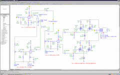
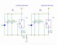
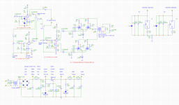
'ere's version 1, standard PP no global feedback. Provision for an FX in/out loop, which allows me to not use only the power section onwards. CCS uses 7805 regulators, for a 50mA constant current through a 100 Ohm resistor.
The library does not have a UL transformer, so the power sections are currently triode-connected. I am planning on pentode and UL connections too. Also, PS schematic is not shown, as I am not really confident of the voltages used.
Brickbats welcome. My main issue is how close to the edge the triodes are running (max Pa of triodes is 0.5W as per datasheet). This is sort of deliberate, so I don't run out of drive current. Could back it off significantly if required/advised.
Attachments
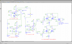
Yes 0.22uF is a bit too big for guitar amp use. Try 22nF or as Jim suggests 10nF.
I only had a quick look at your proposed schematics but noted the following:
MOSFET M1 needs a 220 Ohm or biggger (no need to go over 1K) gate stop resistor. The propensity for parasitic oscillation is roughly inline with a devices gm. Mosfets have X100 to X1000 the gm of a typical audio output pentode and so you can assume that without a gate stop they are X100 to X1000 times as likely to go into parasitic oscillation.
The concertina splitter V3a needs some bias components. Probably best to cathode bias it and return R7, C16 etc to the bottom of the cathode bias resistor (bootstrapped input).
Check out some early Fender Schematics - e.g.
http://www.recproaudio.com/diy_pro_audio/diy_files/tweed_deluxe/deluxe_5e3_schem.gif
See the way they biased it?
Don't worry about the 56K vs the 33K anode and cathode loads. The triode section of your 6GV8 is "grunty'er" than a 12AX7 triode section so you can use the 33K you had shown.
If you want to get fancy you can use LED(s) in place of the bias resistor. IR and Red LEDS about 1.4 Volts, Green LEDs about 1.8 to 2.0 Volts.
When you go to pentode mode the 2K grid stop resistors on the output pentodes will want to be MUCH larger (suggest 47K) to help prevent blocking distortion and improve the overdrive sound.
Cheers,
Ian
Last edited:
Thanks for the help
I chose 0.22 randomly, and I will back those down to 22 and 10nF. I may have so high voltage 22nF types already, saves me a few more pennies.
I will perform the rest of the changes on the schematic and part values, and hope to fire up the iron soon. I am still a bit confused about bias I guess, but I hope to have that figured out after a few builds.
Bias (the basics):
Devices come in 2 types.
Enhancement Mode Devices, like Transistor and Mosfets. With no bias they are OFF, you have to apply some "bias" voltage to get them to conduct current.
Depletion Mode Devices, like TUBES and JFets. With no bias they are ON "flat out" - conducting maximum current. you need to apply some "bias" voltage to limit the current or turn them off.
For a tube you want the grid to be at a negative voltage with respect to the cathode to control the tube current. This is the same as saying you want the cathode to be at a positive voltage with respect to the grid, and that is the way we normally arrange it in practice.
You put a bias resistor in the cathode circuit and tie the grid reference back to the bottom of that resistor. The bottom of that bias resistor might be, but does not have to be, at 0V (In this case, for teh concertina splitter, it will not be at 0V, but the grid to cathode voltage is still what controls the current). The voltage drop across that bias resistor when current flows makes the cathode more positive than the grid. The more the current the higher the voltage but the higher the voltage the more the current is "turned off". The circuit will find its own equalibrium.
Want a higher idle current - use a smaller bias resistor and vv.
Cheers,
Ian
Last edited:
Thanks again Ian.
My question was actually the calculations I was using anode load to set the max current through the tube, looks like my current and power calculations are off so I will need to go back and see what those are working out to. For academic interest at least!
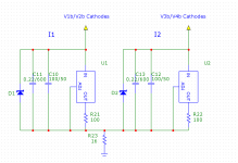
I could not figure out how to change the gate stoppers in pentode mode only, not enough poles on a switch (I assume to help with the increased miller capacitance in pentode mode?), so I'm just using a single value now and hopefully it will work in all the proposed modes.
Eventually I hope to evolve a preference for a specific type of configuration. In all the hifi amps I've heard, I seem to prefer UL modes or amps configured permanently in UL. I suppose it might not be the same for guitar.
I'm guessing I might get about 10-12W out of this thing in Triode mode, which is enough for me and hopefully has a sound decent enough to record some basic stuff with. Not really looking for much overdrive, basically some soft clipping. Like an old Fender, rather than Marshall. That is why I haven't yet put in a bridge rectifier.
Really appreciate all the help I'm getting.

Cheers!
My question was actually the calculations
I was using anode load to set the max current through the tube, looks like my current and power calculations are off so I will need to go back and see what those are working out to. For academic interest at least!I could not figure out how to change the gate stoppers in pentode mode only, not enough poles on a switch (I assume to help with the increased miller capacitance in pentode mode?), so I'm just using a single value now and hopefully it will work in all the proposed modes.
Eventually I hope to evolve a preference for a specific type of configuration. In all the hifi amps I've heard, I seem to prefer UL modes or amps configured permanently in UL. I suppose it might not be the same for guitar.
I'm guessing I might get about 10-12W out of this thing in Triode mode, which is enough for me and hopefully has a sound decent enough to record some basic stuff with. Not really looking for much overdrive, basically some soft clipping. Like an old Fender, rather than Marshall. That is why I haven't yet put in a bridge rectifier.
Really appreciate all the help I'm getting.
Cheers!
Attachments
- Status
- This old topic is closed. If you want to reopen this topic, contact a moderator using the "Report Post" button.
- Home
- Live Sound
- Instruments and Amps
- 4x6GV8 proposed build