The power amp is self contained (and AC coupled at its input) which rules out any other part of the unit affecting it. DC offset is a voltage quantity, lol, you keep mentioning ohms ")
I thought we had the offset sorted, or at least that it was very low when the wiper of the preset was grounded.
I thought we had the offset sorted, or at least that it was very low when the wiper of the preset was grounded.
Ive found whats wrong with my amp from a thread on AudioKarma.Theyve got a new website and there search engine must not have been working properly when I searched there before for answers to my biasing and offset problems? So out of desperation I tried again and found that the original driver transistors with the small tabs fail with age, the HFE drops to negligible levels.Yet they read fine on a DMM diode test. Someone on AK had identical problems as me so Im going back to using the MJE15030/31 drivers that I was using before and 2SA914/2SC1953 instead of 2SA818 and 2SC1628 But they will be brand new ones just in case.Thanks for the help Mooly! Its been fairly frustrating on the odd occasion not knowing what to do next But who wouldve thought of low HFE? I can now in hindsight, the feeble scratchy right channel and the left channel was crap as well. At least Ive got a pretty good idea on how the driver and power amp works now.
Excellent, well done
I'll have to remember that one because the faults/symptoms you were getting just didn't seem to fit anything like that... but yes, old (and mainly Japanese) devices can do strange things. I just never suspected yours of that.
http://www.diyaudio.com/forums/solid-state/163888-vintage-reliability.html#post2133465
http://www.diyaudio.com/forums/soli...-d315-repair-troubleshooting.html#post3392755
http://www.diyaudio.com/forums/soli...ilure-nad-7225pe-suggestions.html#post2754632
Dont forget those wiring problems throwing a red herring into the works! But failing transistors is about all it can be Mooly? Because Ive checked all the components,done continuity tests on all the tracks and cleaned any pins that may have become oxidized so the solder wouldnt take.Ive gone over the board with a jewlers loup cleaning off flux and checking everything and those old transistors have got to be the problem. After reading those links you put up Im even more convinced but theres always that bit of doubt in the back of my mind until Ive finally nailed it. Ha! It will take a few weeks to get the new transistors from England, Ill let you know what happens then?
I know, you were seeming to get different symptoms every time
My experience with the failing transistors in those links is that they actually fail open circuit B to E (and its measurable as a high B-E voltage in circuit), and in doing that it would then show as a 'hard' fault and give a rail value DC offset. That's why I didn't really suspect yours of doing that... but low gain... hmm... an unusual one for sure.
Anyhow, onward and upward
I know, you were seeming to get different symptoms every time
My experience with the failing transistors in those links is that they actually fail open circuit B to E (and its measurable as a high B-E voltage in circuit), and in doing that it would then show as a 'hard' fault and give a rail value DC offset. That's why I didn't really suspect yours of doing that... but low gain... hmm... an unusual one for sure.
Anyhow, onward and upward
OK Ive received the 2SC1953 transistors and installed them.Ive reinstalled all the MJE15030/31 drivers and cleaned off some blackleg starting to appear on 2SA562 and 2SC735. I set both sides DC offset and the right channel bias to 50ma but the left channel wont go past 24ma with the trimmer turned fully anticlockwise? I checked the Beta on the NOS drivers when I took them out, well four of them anyway because the other four had their collectors cut off to go on the heatsink. One was 58, 2 were 86 and one was 190. Ive done all the diode,transistor and continuity checks,reflowed all the joints again and now Im at a loss to do anything? Any ideas Mooly
If the offset is now OK, and the only apparent problem is low bias on one channel then the amp should actually be working and sounding fine.
Can you confirm that is the case before we look at altering anything ?
The right channel sounds great.The left channel is crap,I can hardly hear it. I turned the left bias trimmer down to match the right trimmer,that bought it down to 10ma or 390 ohms the same as measured across the right bias trimmer that reads 50ma I did that just in case it jumped to full on bias because I had the trimmer turned all the way to zero resistance to get the 25ma.I wont fall that trick again, I blew 2 outputs when that happened last time.
If the sound level is faint, it could be a problem with the components that fix the closed loop gain. The capacitor in the RC that decouples the feedback to earth passes a.c. and should block d.c. but if it has become open circuit more or less through degradation or failure that could account for this and possibly some dc issues.
We need to be clear on this, its so important to get this right.
Is it just low level but otherwise OK ? (or is it distorted).
Faced with these symptoms here is what I would do...
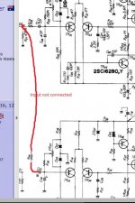
1/ Confirm that the signal reaching TR01 and TR02 base are nominally similar. That's a basic test, proving that the faulty channel is actually receiving a known good signal.
2/ Be absolutely sure on the bias problem. This is important. Look at the four 0.33 ohms in the faulty channel. With no signal and no speaker connected you should have 'some' bias current flowing. If you have at least 2mv (yes that small) DC voltage across each 0.33 ohm then sufficient current is flowing for the amp to work.
The left channel is crap,I can hardly hear it.
Is it just low level but otherwise OK ? (or is it distorted).
Faced with these symptoms here is what I would do...
1/ Confirm that the signal reaching TR01 and TR02 base are nominally similar. That's a basic test, proving that the faulty channel is actually receiving a known good signal.
2/ Be absolutely sure on the bias problem. This is important. Look at the four 0.33 ohms in the faulty channel. With no signal and no speaker connected you should have 'some' bias current flowing. If you have at least 2mv (yes that small) DC voltage across each 0.33 ohm then sufficient current is flowing for the amp to work.
If the sound level is faint, it could be a problem with the components that fix the closed loop gain. The capacitor in the RC that decouples the feedback to earth passes a.c. and should block d.c. but if it has become open circuit more or less through degradation or failure that could account for this and possibly some dc issues.
Thanks mate,Ill check that out.
The left channel is too low to hear it properly,its barely there! I would say its distorted though.I checked every voltage on the transistor pins against the good side and they all matched closely. How would I know if a good signal is getting to TR01 or TR02 without an oscilloscope ? Ill check to see if Im getting at least 2mv DC across each 0.33 ohm resistor tomorrow because it 2.10am here. Ill get back to you in the morning Mooly.
We need to be clear on this, its so important to get this right.
Is it just low level but otherwise OK ? (or is it distorted).
Faced with these symptoms here is what I would do...
1/ Confirm that the signal reaching TR01 and TR02 base are nominally similar. That's a basic test, proving that the faulty channel is actually receiving a known good signal.
2/ Be absolutely sure on the bias problem. This is important. Look at the four 0.33 ohms in the faulty channel. With no signal and no speaker connected you should have 'some' bias current flowing. If you have at least 2mv (yes that small) DC voltage across each 0.33 ohm then sufficient current is flowing for the amp to work.
There is also a question whether the testing is being done with the safety light bulb in series with the mains or not.
If it is and the closed loop gain is only one then driving the system harder to increase the volume will give rise to distortion by overloading the input transistor.
I looked up a service manual re the capacitor in the nfb decoupling RC arm to zero volts. This should be a bipolar 470uF of 6.3 volts rating - but it would be worth checking that it really is if the previous owner has done modifications, and, to check the solder joints where the network connects to zero volts.
I don't use the safety bulb method to limit current but understand the wattage rating needs to appropriate to the needs of the amplifier being tested - this one has a rating of 110 watts. I will leave that for your judgment.
Low wattage light bulbs have been used as the control element to create positive feedback in simple oscillator circuits whereas the safety bulb has been induced to light up on tests when seemingly minor changes or adjustments have been made. My impression was of working on some cusp of stability.
The power stages of the amplifier draws the most current however if the bulb chokes the supply too much, the possibility it is constricting the LTP and VAS stages and the separate preamplifier stages as well.
A PSU (bulb) problem would tend to affect both channels more or less equally.
Lift the 10k at the input to the faulty channel and cross couple it to the good one such that each channel is receiving the same signal.
How would I know if a good signal is getting to TR01 or TR02 without an oscilloscope?
Lift the 10k at the input to the faulty channel and cross couple it to the good one such that each channel is receiving the same signal.
A PSU (bulb) problem would tend to affect both channels more or less equally.
True but then there are two of them - I take it you are happy with the wattage of the bulb being used - in which case the supply rails for the pre-amp section should be in line with the specifications.
I note also that the output transistors in the amplifier were SB and SD types which have been replaced by MJL21193 and MJL21194 which have a lower cut off frequency - apparently only in the faulty channel.
Last edited:
The replacement transistors MJ's not MJL's would reduce the loop stability margin so there is a question on how to address this.
I have some unused SB 645's and SD 665's devices you can try - Gratis in the spirit of ANZAC.
The original outputs were 2SA747 and 2SC1116,replaced with MJ21193/94. I think you have mistaken the final drivers 2SD383 & 2SB537! Ive replaced those with MJE15030/31. Thanks for the offer anyway. Youre just up the track from me I see!
A PSU (bulb) problem would tend to affect both channels more or less equally.
Lift the 10k at the input to the faulty channel and cross couple it to the good one such that each channel is receiving the same signal.
Ive got +5.4mv and -5.8mv across an 0.33 ohm output resistor on the good right channel. The left channel has +0.0mv and -0.2mv across an output resistor. If I lift the 10k ohm resistor on the left channel,do I connect the 10k resistor to where on the right channel,at the same place as the other 10k resistor? Another thing Ive noticed is the changing voltage from the big cap power supply,with the DBT connected it will be 50v,then maybe 46 volts,then something else.today its 43.6 volts? I dont know if its the load or the power supply itself but Ive checked the PS a few times before and cant find anything wrong there?
Last edited:
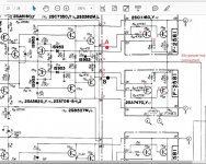
Lets stick with the easy stuff The 10k is done like this. Lift one end and wire it to the good channel as shown here.
If the bad channel has no bias current (0.00 volts across 0.33 ohm confirms that) then there may be a problem with the output stage.
Put your red meter lead on point A and black on point B. The voltage should be around 1.4 volts and should be alterable with the bias preset. As the voltage approaches 1.4 volts then the output stage should start to conduct and current flow. Be careful, don't blow anything up.
Also compare this voltage with the good channel for reference.
The 10k is done like this. Lift one end and wire it to the good channel as shown here.If the bad channel has no bias current (0.00 volts across 0.33 ohm confirms that) then there may be a problem with the output stage.
Put your red meter lead on point A and black on point B. The voltage should be around 1.4 volts and should be alterable with the bias preset. As the voltage approaches 1.4 volts then the output stage should start to conduct and current flow. Be careful, don't blow anything up.
Also compare this voltage with the good channel for reference.
Attachments
The original outputs were 2SA747 and 2SC1116,replaced with MJ21193/94. I think you have mistaken the final drivers 2SD383 & 2SB537! Ive replaced those with MJE15030/31. Thanks for the offer anyway. Youre just up the track from me I see!
I did not enlarge the file sufficiently and missed that. SA and SC transistors have a higher cut of frequency, than SB and SD types, which in turn have a higher cut of frequency than the MJ's. The difference between SA and SC transistors and MJ's could be as much as a decade. I don't have any SA and SC transistors to help you out so I will keep out of the discussion you have been having with Mooly.
- Status
- This old topic is closed. If you want to reopen this topic, contact a moderator using the "Report Post" button.
- Home
- Amplifiers
- Solid State
- 47 volts on output resistors?