So... if the bulb is lit with TR19 and TR21 removed you either have failed output devices, incorrect wiring somewhere or the short is elsewhere.
Next step would be to remove both pairs of outputs and make sure the bulb is OFF. Assuming it is, you could then fit one pair of known good outputs as a test... the amp would work OK with a single pair.
If the bulb was still lit then the current draw isn't coming from the output stage... its something else entirely.
So... if the bulb is lit with TR19 and TR21 removed you either have failed output devices, incorrect wiring somewhere or the short is elsewhere.
Next step would be to remove both pairs of outputs and make sure the bulb is OFF. Assuming it is, you could then fit one pair of known good outputs as a test... the amp would work OK with a single pair.
If the bulb was still lit then the current draw isn't coming from the output stage... its something else entirely.
Hmmm! I wonder if its those MJ21194s that I pulled from a blown up Crown amp? It had some blown ones but these ones measure OK and they are working on the other channel? Ill remove both pairs of outputs and see what happens.Ill get stuck into it in the morning,its 2am now. Thanks Mooly.
I removed both pairs of outputs and the DBT still lights up. I disconnected the 55v power positive then neg but it still lights up? So I suppose its back to the driver board? This is weird but from experience I know Ill kick myself when I find its some simple thing Ive overlooked.Ill let you know if I find whats wrong Mooly.
Something is still lighting up the DBT! I desoldered the link from TR09, took the outputs out again and tried powering up,then without the 55v power to the left channel then I tried taking the output to driver board connectors out one by one and it still lit up until I got to the last one.NPN on the right channel and the green light came on. I had the input plug from the pre-amp unplugged as well so its got to be on that board somewhere? Im going gold prospecting out in the bush this Saturday for a rest. lol
Attachments
Last edited:
Its getting very confusing when talking about two channels ")
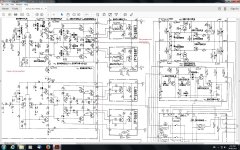
Lets go back to basics. If you isolate all the output devices (all eight), does the bulb tester light ?
Assuming it DOES NOT, we pick a single channel to work on and to get operational. With the outputs isolated we should have zero volts on points 17 and 10 on the main board.
The offset trimmer should work and allow the output (points 17 and 10) to be set to zero.
The bias trimmer should work by allowing the voltage across each of those 68 ohm emitter resistors (on the drivers) to reach at least 1 volt DC in one direction and to be able to lower it to less than 300mv in the other direction. If that is proved OK then finish up by turning the bias trimmer to the end that gives the lowest voltage across the 68 ohms.
That should prove the main board OK. That's the point we add a single output pair and continue testing.
With all outputs disconnected and green power light on (DBT off) I get +599mv on left channel and +535mv on right channel. Both trimmers are unresponsive,I turned them both fully anticlockwise and the readings stayed the same. I plugged that right channel NPN connector in before doing anything and I got 75mv on the right channel.If I turned it any which way it would show that it was working then bounce back to what it was,75mv? I will post a photo of the driver board front and back when its daylight tomorrow.Maybe you can see something wrong that I cant? The photos have glare on them from the lights otherwise!
Last edited:
OK, lets work with the 500 to 600 hundred mv offset as measured at the output.
Is the bias current adjustment trimmer altering the voltage across those 68 ohm resistors as I mentioned above ?
All the 68 ohm resistors read 0000mv and unresponsive except for R64. It reads 116mv and after about 4 or 5 turns of the bias trimmer it went to 88mv across the resistor.
 I havent put the outputs etc,back in yet!
Last edited:
OK. So just to confirm... at this stage we still have around 600mv DC offset and also unresponsive bias pots.
So we do three further checks to try and see why the bias pot is not working.
1/ The voltage across R27 and R28 (they are the 120 ohms connected to the emitters of TR07 and TR08) should have around 0.7volts across them.
2/ This is an important one. The voltage across TR09 and TR010 (that's C to E) should alter as the bias preset is turned. It needs to reach at least 4.5 volts or so in order to turn all the drivers and outputs on.
(Why 4.5 volts... we have two drivers and an output in each half. That's 6 transistors to turn on and so we need 6 times 0.7 volts (around 4.2 volts as a minimum) in order to do that)
3/ With an offset of less than 1 volt, you should also be able to measure approximately the same voltage on the bias transistors TR09 and TR010.
OK. So just to confirm... at this stage we still have around 600mv DC offset and also unresponsive bias pots.
So we do three further checks to try and see why the bias pot is not working.
1/ The voltage across R27 and R28 (they are the 120 ohms connected to the emitters of TR07 and TR08) should have around 0.7volts across them.
2/ This is an important one. The voltage across TR09 and TR010 (that's C to E) should alter as the bias preset is turned. It needs to reach at least 4.5 volts or so in order to turn all the drivers and outputs on.
(Why 4.5 volts... we have two drivers and an output in each half. That's 6 transistors to turn on and so we need 6 times 0.7 volts (around 4.2 volts as a minimum) in order to do that)
3/ With an offset of less than 1 volt, you should also be able to measure approximately the same voltage on the bias transistors TR09 and TR010.
Thanks for that Mooly, Ill check it all out and get back to you on whats happening with this bloody thing? I was just thinking ,what if the pos or the neg power to the driver board was intermittent! Would that cause the DBT to light up do you think?
Last edited:
Im just back from my prospecting trip, got a few nice bits of gold,I needed that because this amp was getting to me.lol I put it all back together and installed the last of the transistors from the F-2583 driver board,they were the last ones before going to the outputs and bingo the DBT only has an above average dull glow now as if its been biased a bit too far! I havent done the R27/R28 0.7v test or the T09/T10 C to E voltage test yet,I thought Id turn the amp off and report this in case I stuff anything up.The left channel has 200mv and the right channel has 4.00v DC offset?
Attachments
Last edited:
It sounds like you are changing parts and getting different symptoms every time.
Neither offset value suggests a 'hard fault' such as a transistor etc. That would normally cause the output to swing to one rail.
Do you have an oscilloscope available to be able to se if there is any sign of oscillation on the output ?
Also, are you able to obtain zero volts on the wiper of each channels DC offset trimmer ? If you can't get the voltage here to adjust between + 0.7, then through zero and to -0.7 then you will never set the offset correctly.

Ive got an oscilloscope but its got a short in the power supply! I noticed that I hadnt plugged the right channel posistor back in and when I did the 4v Offset went down to 220mv but the left channel went up from 200mv to 1.5v? I adjusted the right channel to under 1mv but when I adjusted the left channel the relay clicked the green light came on and the amp come out of protection at 1v DC offset? I kept adjusting anticlockwise until it clicked at the end of its travel and still had 500mv reading on the DMM? I left it for a while and it started climbing from 500mv to 680mv when I turned the amp off. R27 reads .580v across itself and R28 reads .603v TR10 on the right side reads 3.8v C to E. TR09 reads 3.6v across C to E.
The two channels shouldn't be interacting at all... that doesn't make sense... or maybe its a thermal or instability issue that just makes it seem that it altered as you set the offset on the right channel.
The voltages across TR09 and TR10 sound fine but you should be able to bring the voltage low enough that the bias current falls to zero.
Lets start again.
1/ Force the bias current to zero by shorting TR09 and TR10 C to E.
2/ Concentrate on the offset. Make sure you can swing the offset preset wiper from +0.7 to -0.7 as I outlined above.
If you can't achieve that then we have a problem around the preset.
If it does adjust OK then set the wiper to voltage to around zero.
3/ In this state the amplifier output offset voltage should be very low, it should be stable and the amplifier should work essentially normally and play music.
Yes, lets do both channels the same and see where that gets us. The quiescent current in the output devices should be zero with no load attached and the DBT should be pretty much out.
The DBT has gone bright again? All I did was reflow the right channel offset pot pins and a few solder joints around it before I got around to shorting the bias transistors TR09/10. Im a bit sore from using muscles that Ive forgotten about so I think Ill have an early night and short those transistors in the morning,then report back with the results.
- Status
- This old topic is closed. If you want to reopen this topic, contact a moderator using the "Report Post" button.
- Home
- Amplifiers
- Solid State
- 47 volts on output resistors?