Now there is only one IC 21844. I want to achieve that everything works well with one chip, then I'll add others. Because already 10 output transistors are damaged.
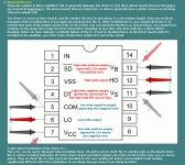
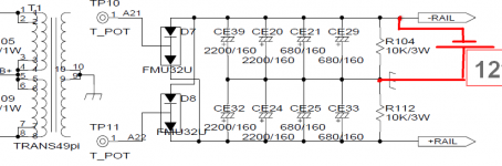
If I measure the resistance between 11 and 12 pins with the polarity of the probes as in the figure, it shows 30 KΩ, and if the negative probe is 12 pin, it sometimes shows 4.7 KΩ and sometimes 17 KΩ.
If I measure the resistance between 11 and 12 pins with the polarity of the probes as in the figure, it shows 30 KΩ, and if the negative probe is 12 pin, it sometimes shows 4.7 KΩ and sometimes 17 KΩ.
When measuring the voltage on regulators, it's often better to place the black probe on the regulator's ground terminal and the red alternately on the other two terminals. Here it didn't really make a difference.
Confirm that the 12v is reaching the driver board pads by reading across pins'pads 5 and 7 (black probe).
Re: post 26.
Can you lift either pin (11 or 12) and measure the resistance them with out the connection to the board?
Confirm that the 12v is reaching the driver board pads by reading across pins'pads 5 and 7 (black probe).
Re: post 26.
Can you lift either pin (11 or 12) and measure the resistance them with out the connection to the board?
Hi. I again decided to deal with this amplifier. I want to remove the rectifiers and connect a 12v lead battery to the high-side. What is the minimum capacity for this battery?
How battery should be connected? As in the picture?
There is no misprint, exactly 1 OM? Calculation shows that with this resistance, the initial charge current of the capacitors will be 12A.If you use a 9v battery, you should insert some sort of over-current protection. A 1 ohm 1/8w resistor would work. A 1 amp fuse should also be OK.
How battery should be connected? As in the picture?
Attachments
- Status
- This old topic is closed. If you want to reopen this topic, contact a moderator using the "Report Post" button.
- Home
- General Interest
- Car Audio
- 4000.1