Hi all,
I searched and couldn't find a thread on these boards, now common on Aliexpress and eBay and I'm sure plenty of others. Audiophonics has a slightly different version (I think it is a previous revision of the same board but with a different pin out).
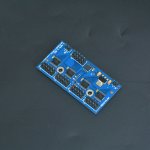
Anyway, the principle of operation is that it runs off 5V, uses a microcontroller to switch from one input to another. The lines are switched through 4x 74HC573 D type latches, and each of these is turned on or off via a (momentary, NO) repeated button press via an STC15W101 controller. Upto 8 lines can be switched per input (10 pins) with 2 ground pins. There are different levels on information out there available on these - the Aliexpress info tends to be short, but some ads on eBay contain a bit more info.
I've managed to let the magic smoke out of two of these now, so I can say they aren't super robust, but outside of that do certainly work. On the first one that I killed, I had grounded some of D1-D8, and you'll see in the quoted text below that this is not recommended. In the second case, I believe that I hit a short and some current flowed through the ground. The end effect is that one input stops working in such cases - in essence it becomes a 3 input switch. What I don't know at this point is whether the microcontroller has been killed, or one of the latches. - I will try to figure that out when I get some new parts here.
The text from eBay is quoted here, and you'll see there is reference to the two pinouts.
I've posted this here for comments and any obs anyone might have. I think if there is a way to make this unit more robust, it might be worth it.
I searched and couldn't find a thread on these boards, now common on Aliexpress and eBay and I'm sure plenty of others. Audiophonics has a slightly different version (I think it is a previous revision of the same board but with a different pin out).
Anyway, the principle of operation is that it runs off 5V, uses a microcontroller to switch from one input to another. The lines are switched through 4x 74HC573 D type latches, and each of these is turned on or off via a (momentary, NO) repeated button press via an STC15W101 controller. Upto 8 lines can be switched per input (10 pins) with 2 ground pins. There are different levels on information out there available on these - the Aliexpress info tends to be short, but some ads on eBay contain a bit more info.
I've managed to let the magic smoke out of two of these now, so I can say they aren't super robust, but outside of that do certainly work. On the first one that I killed, I had grounded some of D1-D8, and you'll see in the quoted text below that this is not recommended. In the second case, I believe that I hit a short and some current flowed through the ground. The end effect is that one input stops working in such cases - in essence it becomes a 3 input switch. What I don't know at this point is whether the microcontroller has been killed, or one of the latches. - I will try to figure that out when I get some new parts here.
The text from eBay is quoted here, and you'll see there is reference to the two pinouts.
I've posted this here for comments and any obs anyone might have. I think if there is a way to make this unit more robust, it might be worth it.
Four-way audio I2S / IIS switching module! Choose one out of four! I2S buffering! I2S 4 choose 1 module!
The default price is for loose parts
!!
The function of this module is up to four I2S signal inputs. Select one of them to be transmitted to the following DAC decoder and other equipment! (You can only select one of the four channels for use, you cannot combine four channels into one channel). . .
This module is controlled by a single-chip microcomputer (a single-chip microcomputer has been integrated on the board and the program has been written, and the buyer does not need to use the single-chip microcomputer to control it). The buyer only needs to use an external button to choose which signal to use (note that the external button is a key (unlocked) It is not a switch), and has a power-off memory function (the signal selected last time is automatically used when the next power-on). When using one signal, completely block the other three signals to avoid interference. Each signal can transmit a maximum of 8 signal lines, in addition to 4 used to transmit I2S signals, the remaining four can be used to transmit other signals such as DSDON signal mute signal, etc. (of course, the remaining four lines can also be used to transmit another group of I2S For four-channel use, how to use it can be freely played).
Detailed introduction:
The IN-A IN-B IN-C IN-D connector on the board is four-way signal input. The OUT interface is an output. The But interface is used to switch signals using external keys. The POWER (or + G) interface supplies 5V DC to the power interface.
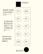
The interface definition of the new version was updated on July 27, 2019. For users who purchased before, please check the definition of the old version!
The definition of the input and output interface is as follows (note that the new version and the old version are distinguished, the new version of the board has a square and dot identifier, the old version is marked with the number 1 next to the interface): the input and output interface definitions are the same but the signal direction is different -C IN-D direction is input, OUT direction is output!
It should be noted that when one of the signal lines such as D1 is used as a DATA data line, then D1 of all input and output interfaces must be used as DATA; D2-D8 is the same reason.
Note: The GND of each board can only be connected to GND. D1-D8 cannot be used as GND! D1-D8 can only be connected to signals and cannot be connected to the front and rear boards instead of GND! !! !! When connecting to the GND of the front and rear boards, you can only use the GND pin! !! !! !! !!
Connect + of the power interface to 5V G to GND. The wrong connection will damage the board!
When the But interface is connected to the button, the two wires of the button must be connected to the But interface. Please do not lead from other places. The two wires connected to the button cannot be connected anywhere else, otherwise you will be responsible for any problems!
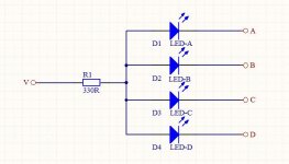
A B C D V 5 single-character interfaces on the board are used for LED display (new V character is changed to 3.3V)!
Attachments
I made another little discovery on these switches - they can be set to switch between 2, 3 or 4 inputs. To do this, close the "but" selector button at power on - doing this repeatedly will cycle through the modes. This had me really puzzled for a while!!
This is why I thought I had damaged the first one (let the magic smoke out comment above) - it turns out I didn't damage it I think, I just had the contacts closed at power up and therefore on power up it went to 3 inputs and so on.
OK, so given that they seem reliable now that I figured that out, it seems that it is not worthwhile trying to reinvent the wheel, especially when these are <10e each.
Small input series resistors would improve ruggedness somewhat, as would back-to-back Schottkys to each rail. The small performance penalty may, or may not, be worth it to the user -- YMMV.
Sounds like the 'But' interface could use some 'range / current limiting', too.
Cheers
Sounds like the 'But' interface could use some 'range / current limiting', too.
Cheers
Last edited:
Sweet. I just tested this board and it seems to work as described. I just have one question which I don't believe is covered in the (slightly confusing) instructions above... I've configured my board as a 4in to 1out switcher. Can I apply 5v to one of the vacant pins on the output so that whichever input I select, that input would get 5v on it's corresponding pin?
Ex: If I connect 5v to output pin D6, when I select input A, 5v will be sent to pin D6 of input A to power something like a Bluetooth module.
This way the Bluetooth module will only get 5v power while A is selected, then turn off when another input is in use.
Thanks
Ex: If I connect 5v to output pin D6, when I select input A, 5v will be sent to pin D6 of input A to power something like a Bluetooth module.
This way the Bluetooth module will only get 5v power while A is selected, then turn off when another input is in use.
Thanks
The short answer is.... I don't know.
But I imagine that the datasheet for the chip would tell you what current they can handle - probably something quite low like 10-20mA. I also don't know if it will take reverse voltage as I think you are suggesting?
Maybe the thing to do is to use the signal from the controller chip to turn on a transistor that handles the power to the bluetooth module?
- Home
- Source & Line
- Digital Line Level
- 4-way i2s switches