Backhanded Encouragement
Graham,
When we say 'your crazy ideas', we mean that in the nicest possible way, of course.
Indeed it is very interesting to hear of your experiments.
Your expose on modifying MWO transformers was excellent - I have thought I using these myself, but had discarded the idea because I thought that they were permanently welded shut, but your closer observation reveals that they can be hacked.
I kick myself for not taking a close enough look.
Eric.
Stuff and anti-stuff.
Complementary symmetry this time. As with the others, no need for global feedback because the output of the regs track the input within a fraction of a millivolt. Voltage gain is x1. Set bias by changing 2R4 resistor. Has constant 2.5 volts across it. Currently = 1 amp so operates in class A. Any oscillations can be damped by putting a 100nF between adj and out pins of each reg.
Complementary symmetry this time. As with the others, no need for global feedback because the output of the regs track the input within a fraction of a millivolt. Voltage gain is x1. Set bias by changing 2R4 resistor. Has constant 2.5 volts across it. Currently = 1 amp so operates in class A. Any oscillations can be damped by putting a 100nF between adj and out pins of each reg.
Attachments
If you compare the the '317 with an NPN, the base is 0.7v higher than the emitter, with the '37 the ADJ is 1.25v lower than the OUT. This 1.25v stays put come hell or high water though. No temp compensation necessary. Yep, class AB would be nifty, but with the cct I drew if you raise the resistor value the currents in the two output coupling capacitors would become assymetrical and the voltage across them would change and so would the bias.  What it needs is some sort of constant voltage drop thingy between the OUT's instead of a resistor, something like a couple of forward biased diodes. Actually a *way* better setup would be to join the two OUT's, get rid of the resistor, and use just one output coupling cap. Separate the two ADJ's from each other and make the upper one lower by 1.25 volts, and the lower one higher by 1.25 volts. Capacitively couple them, bias them to half rail (well, the imaginary midpoint between them to half rail seeing they are 2.5 volts apart) and feed signal in as before. Only trouble is, unlike a BJT output stage where the current gradually comes on with bias, with this one the current comes on most suddenly once you exceed that 1.25 / 2.5 volts bias. Only way out that I see is to put a 0.1 ohm or so resistor between each OUT and output coupling cap just as in a conventional BJT output stage. But then the output impedance rises to 0.1 ohms, and would have to have a feedback loop to lower it if you really wanted to. In reality though it would probably be quite ok this way. I'll have to give it a go too because I really want to try class AB too. One you are running a bare minimum of current I can't imagine crossover distortion would be an issue at all courtesy of that 80dB feedback inside the regs.
What it needs is some sort of constant voltage drop thingy between the OUT's instead of a resistor, something like a couple of forward biased diodes. Actually a *way* better setup would be to join the two OUT's, get rid of the resistor, and use just one output coupling cap. Separate the two ADJ's from each other and make the upper one lower by 1.25 volts, and the lower one higher by 1.25 volts. Capacitively couple them, bias them to half rail (well, the imaginary midpoint between them to half rail seeing they are 2.5 volts apart) and feed signal in as before. Only trouble is, unlike a BJT output stage where the current gradually comes on with bias, with this one the current comes on most suddenly once you exceed that 1.25 / 2.5 volts bias. Only way out that I see is to put a 0.1 ohm or so resistor between each OUT and output coupling cap just as in a conventional BJT output stage. But then the output impedance rises to 0.1 ohms, and would have to have a feedback loop to lower it if you really wanted to. In reality though it would probably be quite ok this way. I'll have to give it a go too because I really want to try class AB too. One you are running a bare minimum of current I can't imagine crossover distortion would be an issue at all courtesy of that 80dB feedback inside the regs.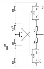
I am going to make a complementary symmetry buffer using an LM317 / LM337 combination
Ok, how about applying the same idea to a pair of switching regulators - like the 'simple switchers' to give us a nice hefty 12v powered monster amp?
hmmm.... it's set me thinking.....
ray
Ok, how about applying the same idea to a pair of switching regulators - like the 'simple switchers' to give us a nice hefty 12v powered monster amp?
hmmm.... it's set me thinking.....
ray
Hah! I ended up trying almost exacty that! I used a TL431 and a pot instead of a transistor, but it's the same principle. Definitely had to use a 10R in series with 100nF across the speaker to stop it oscillating sometimes. Also a 100nF from adj to out on the '317 only. At low levels I could get it run at 15mv p/p output with 10mA bias and zero xover distortion. At much higher levels the waveform would get a pair of notches in it unless you wound the bias up to about 50mA. It was a bit of a pig for oscillation sometimes though.e96mlo said:Maybe this would work then...
/Marcus
 My favourite has been the Tetrahedron version. That was very well behaved, that one.
Ray, the switching one sounds cool!
4PH on steroids.
Righto, here it is. The original cct beefed up for some real power. The LM338 has a 5 amp continuous 12 amp peak rating. The fet above the reg bootstraps the supply to the reg to minimise the dissipation in it and also allows way higher supply rails and therefore output swings. In theory, if you put in a 1200v IGBT.... The fet may need a bit of capacitance between gate and source in case it wants to oscillate. I haven't actually built this one up to find out how it goes but you could probably get about 50-70 watts into 8 ohms with a 40v supply. To get the quiescent current set right, if it turns out the choke doesn't have exactly the right resistance, just raise or lower the bottom end of the 4k7 input resistor to get the bias current right. Again, I must stress I haven't built this one, therefore leaving it up to you to 'boldly go where no diyer has gone before'.
The reg is an LM338, NOT LM358 like the drawing shows!
Righto, here it is. The original cct beefed up for some real power.
The LM338 has a 5 amp continuous 12 amp peak rating. The fet above the reg bootstraps the supply to the reg to minimise the dissipation in it and also allows way higher supply rails and therefore output swings. In theory, if you put in a 1200v IGBT.... The fet may need a bit of capacitance between gate and source in case it wants to oscillate. I haven't actually built this one up to find out how it goes but you could probably get about 50-70 watts into 8 ohms with a 40v supply. To get the quiescent current set right, if it turns out the choke doesn't have exactly the right resistance, just raise or lower the bottom end of the 4k7 input resistor to get the bias current right. Again, I must stress I haven't built this one, therefore leaving it up to you to 'boldly go where no diyer has gone before'.The reg is an LM338, NOT LM358 like the drawing shows!
Attachments
more more more...
Time to crank up the wick a bit. Instead of going to a fancier reg for higher power output as per the previous cct, another way to increase the current capacity is to add a PNP transistor to the reg (back to an LM317 again) so the combination functions as a complementary feedback pair, or Sziklai pair. Actually, if you turn this part of the cct horizontal you will probably recognise it as a standard technique for getting higher output from a standard three terminal reg. The current is now only limited by the capacity of the PNP. The '317 reg can manage about 1.5 amps base drive so that should be enough for most situations. The good part about this cct is that the PNP only has about 6 volts across it so no matter how much current you pull through it, there is no worries about second breakdown. Also, you can use quite a slow transistor because the voltage across it changes very little unless you swing to within 6 volts of the positive rail. Quiescent current should be set to supply volts / load resistance. E.g. 32 volts / 8 ohms = 4 amps. One way to do this is to add a bit of voltage to the bottom of the input resistor as in the previous cct. Of course 32v x 4 amps equals 128 watts dissipation, most of which will go in the mosfet, but also the theoretical power output will be 64 watts. In practice a little lower.
Reality strikes! I had the thing running on 40v at about 2.5 amps and I was getting 18.75 watts into 6 ohms and I turned it off to set up some fans on the heatsink so I could wind up the quiescent current further, and when I turned back it on... foof! orange flames and black smoke leaked out of the fet. Actually the flames shot out about 30mm where the legs go into the plastic body. But other than that it worked quite well. I decided to give up on it for the night and come inside.
/Circlotron - remembers the old saying - "With power electronics you are always only a microsecond away from misery". Well, with high voltage switchmode type power electronics at least.
P.S. The IRF540 is a bit to small if you want to get *real* power out of this thing. Seeing it dissipates most of the power, the wattage rating should be at least supply volts x quiescent current.
Time to crank up the wick a bit. Instead of going to a fancier reg for higher power output as per the previous cct, another way to increase the current capacity is to add a PNP transistor to the reg (back to an LM317 again) so the combination functions as a complementary feedback pair, or Sziklai pair. Actually, if you turn this part of the cct horizontal you will probably recognise it as a standard technique for getting higher output from a standard three terminal reg. The current is now only limited by the capacity of the PNP. The '317 reg can manage about 1.5 amps base drive so that should be enough for most situations. The good part about this cct is that the PNP only has about 6 volts across it so no matter how much current you pull through it, there is no worries about second breakdown.
Also, you can use quite a slow transistor because the voltage across it changes very little unless you swing to within 6 volts of the positive rail. Quiescent current should be set to supply volts / load resistance. E.g. 32 volts / 8 ohms = 4 amps. One way to do this is to add a bit of voltage to the bottom of the input resistor as in the previous cct. Of course 32v x 4 amps equals 128 watts dissipation, most of which will go in the mosfet, but also the theoretical power output will be 64 watts. In practice a little lower. Reality strikes!
I had the thing running on 40v at about 2.5 amps and I was getting 18.75 watts into 6 ohms and I turned it off to set up some fans on the heatsink so I could wind up the quiescent current further, and when I turned back it on... foof! orange flames and black smoke leaked out of the fet. Actually the flames shot out about 30mm where the legs go into the plastic body. But other than that it worked quite well. I decided to give up on it for the night and come inside./Circlotron - remembers the old saying - "With power electronics you are always only a microsecond away from misery".
Well, with high voltage switchmode type power electronics at least.P.S. The IRF540 is a bit to small if you want to get *real* power out of this thing. Seeing it dissipates most of the power, the wattage rating should be at least supply volts x quiescent current.
Attachments
4PH with gain
All of the previous cct have been buffers, i.e. whatever voltage swing you wanted across the speaker you had to provide at the amp input, albeit at a higher impedance. This one makes more use of the '317' s internal gain. The quiescent current is set by 1.25 volts divided by (in this case) 1.2 ohms for about 1 amp. 14 volts supply is car battery voltage. With no signal output there is a slight hiss if you put your ear right up to the speaker so it would be no good as a headphone amp unless you used an attenuator between the amp output and the 'phones. Also, you may need a 10 ohm resistor in series with a 100nF cap across the inductor just to make sure it is stable in all circumstances. It worked ok without it but I'd feel more comfortable with it. Anyway, voltage gain is now load resistance divided by bottom resistor, so 1 volt peak will drive it just nicely. That's fairly average for most power amplifiers. I fired it up briefly tonight and fed it from the PC sound card speaker output and it sounded quite respectable considering what it is made from. I'm going to put together a second one and bring it inside and put it on the proper system and see what it is like.
So there you go. Probably the worlds simplest low distortion thermally stable true class A power amp using what really amounts to a single ended power amplifier chip. Not in the the same league as the JLH class A, but besides the choke it costs next to nothing and takes about 5 minutes to wire it up point to point. Next I'll have to give a report on the sound.
All of the previous cct have been buffers, i.e. whatever voltage swing you wanted across the speaker you had to provide at the amp input, albeit at a higher impedance. This one makes more use of the '317' s internal gain. The quiescent current is set by 1.25 volts divided by (in this case) 1.2 ohms for about 1 amp. 14 volts supply is car battery voltage. With no signal output there is a slight hiss if you put your ear right up to the speaker so it would be no good as a headphone amp unless you used an attenuator between the amp output and the 'phones. Also, you may need a 10 ohm resistor in series with a 100nF cap across the inductor just to make sure it is stable in all circumstances. It worked ok without it but I'd feel more comfortable with it. Anyway, voltage gain is now load resistance divided by bottom resistor, so 1 volt peak will drive it just nicely. That's fairly average for most power amplifiers. I fired it up briefly tonight and fed it from the PC sound card speaker output
and it sounded quite respectable considering what it is made from. I'm going to put together a second one and bring it inside and put it on the proper system and see what it is like. So there you go. Probably the worlds simplest low distortion thermally stable true class A power amp using what really amounts to a single ended power amplifier chip. Not in the the same league as the JLH class A, but besides the choke it costs next to nothing and takes about 5 minutes to wire it up point to point. Next I'll have to give a report on the sound.
Attachments
Yep. Next thing I want to do is make a complementary symmetry one with the "collectors" to the centre. With "emitters" to the centre and no "emitter" resistors the transconductance is so high that the quiescent current goes from zero to max with about 1 millivolt change in "base" voltage. Also it is really hard to stop it oscillating. With the "collectors" to the centre it will simply be a current source looking into a current sink. Then a bit of negative feedback will make the output impedance come down to earth so it behaves more like a voltage source which is what we (or at least I) really want. The output stage will be inverting so that will be very easy, just like as in an opamp inverting nfb arrangement. Providing I don't have too many stability problems it should make for quite an interesting setup.x-pro said:You realise that what you've built is the current source amp, not a voltage one, which means that the output impedance is high.
One-man show and tell.
Well???? Come on then!! It's been six weeks since Christer's prediction. Isn't someone else going to try out one of these little beasties? They are *really* easy, especially the first one on the thread. Not scary at all. Go on. Pleeeeeeeeaaaaaaaassssseeeee?????Christer said:Let's do some predictions. In a few weeks people will start
discussing the sound of different brands of 317s, used as
amplifiers, of course. In a few more weeks there will be a large
group of people who have built these 317 amps and love them,
provided that the PSU has discrete regulators.
Circlotron
The implications of the statement above in your original post may have much farther-reaching importance than maybe you originally realised, when actually used for their intended application.
Sorry, that's all the clues you get at the moment, but the posters of some of the more light-hearted comments above don't know what they are missing
Andy.
Anyway, they are a linear power IC and they don't really know whether they are processing music or power supply noise.
The implications of the statement above in your original post may have much farther-reaching importance than maybe you originally realised, when actually used for their intended application.
Sorry, that's all the clues you get at the moment, but the posters of some of the more light-hearted comments above don't know what they are missing
Andy.
Sure will, but put a few thousand microfarads of capacitor in series with the loudspeaker to stop dc flowing through it. Also, lift up the opamp input just a little so its output is sitting about half rail. Then report the joyous results.mjq said:I have these parts available, but will the circuit work as a (small) power amp ??
PS Also have a look at the second post in this thread. http://www.diyaudio.com/forums/showthread.php?postid=144509#post144509
Well, I finally built something.
I breadboarded the circuit from post #2 and can report that it does indeed sound quite nice, though I'm still trying to get rid of some hum and hiss (layout and PS noise I'm guessing ).
).
This CCT runs much hotter than I expected, so I'm needing some more heatsinking.
I'll play around with the layout some more, add some more caps to the power supply, and see how goes.
Then, I want more power
PS. most of the parts (one LM317, power transformer and some caps) were recycled from an APC 240va UPS...
I breadboarded the circuit from post #2 and can report that it does indeed sound quite nice, though I'm still trying to get rid of some hum and hiss (layout and PS noise I'm guessing
).This CCT runs much hotter than I expected, so I'm needing some more heatsinking.
I'll play around with the layout some more, add some more caps to the power supply, and see how goes.
Then, I want more power
PS. most of the parts (one LM317, power transformer and some caps) were recycled from an APC 240va UPS...
Re: Well, I finally built something.
http://www.diyaudio.com/forums/showthread.php?postid=152880#post152880
Seeeeeee....! I told all of you it would work.
/ Circlotron - wonders where he is going to find the bribe money to pay mjq.
Suggest you add a big PNP transistor and a resistor to each of your regs like in this post.mjq said:I'll play around with the layout some more, add some more caps to the power supply, and see how goes.
Then, I want more power
http://www.diyaudio.com/forums/showthread.php?postid=152880#post152880
Seeeeeee....! I told all of you it would work.
/ Circlotron - wonders where he is going to find the bribe money to pay mjq.
- Status
- This old topic is closed. If you want to reopen this topic, contact a moderator using the "Report Post" button.
- Home
- Amplifiers
- Solid State
- 4-part Harmony, a 9 watt class A amp using a voltage regulator IC.