I CERTAINLY don't mean to argue, but the comment was 250W and 350W and taken in the context of a lower powr amp with AMPLE current capability, and a higher pwr amy that is "just" squeezing by on specs...
Yes the difference from 200 to 350 is almost double which = 3 db.
Still most subs are current driven and not volatge drivven. High numbers of LM3886 chips will be as good as a a cheap high voltage output pair or two.
For the money it is hard to match the LM3886's.
Yes the difference from 200 to 350 is almost double which = 3 db.
Still most subs are current driven and not volatge drivven. High numbers of LM3886 chips will be as good as a a cheap high voltage output pair or two.
For the money it is hard to match the LM3886's.
Re: Re: 350W Power Amp with LM3886'S
its noticiable only in your electricity meter reading

peranders said:
The difference between 200 W and 350 Watts is 2.4 dB just about noticable!
115 dB compared to 117.4 dB as an example.
its noticiable only in your electricity meter reading
thanks everybody.
well i will do this:
1- measure the + & - rails V,
2- take note of the part numbers of the output transistors (i think that are MOSFET's) & quantity
3- take note of the PSU capacitors value
4- look the transformer to see if there is some value printed
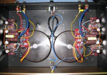
5- take some pictures of the amp.
What can I use for "output load" ? i was thinking to use the speaker... I dont have a 8 ohm 350W resistor
carlmart said:
If the specification has the letters RMS, then it's quite likely close to that power. If it does not then it can be anything.
Two things you can do that do not need a scope:
1) Measure the supply voltage. My guess is a bipolar 170W RMS amp should need close to +/-70v.
2) Count the output transistors on each channel. A bipolar 170w RMS amp should have at least 6 on each side: three NPN and three PNP. They can also be six NPN if it's an old design. Also check the part numbers to see which are their top spec voltages.
Also have a look at the transformer size. Small transformer size and/or few output transistors, even if voltages are high, mean that the output on lower impedance speakers will not be large.
To see the clipping point you do need a scope.
What is the suply capacitance?
If the transformer is large enough and the bridges are heatsinked, you can go up to uF 20,000 with no need to add anything else. BTW: splitting the supply after the transformer with separate bridges and capacitors can be very effective.
It might be a better idea to use that amp to power the RCFs, instead of the 3886s, if the tests I suggest show the 170w may be right.
But to be completely sure you certainly need a 'scope and an output load. This output has to be heatsinked.
Carlos
well i will do this:
1- measure the + & - rails V,
2- take note of the part numbers of the output transistors (i think that are MOSFET's) & quantity
3- take note of the PSU capacitors value
4- look the transformer to see if there is some value printed
5- take some pictures of the amp.
What can I use for "output load" ? i was thinking to use the speaker... I dont have a 8 ohm 350W resistor
zafira1981 said:
What can I use for "output load" ? i was thinking to use the speaker... I dont have a 8 ohm 350W resistor
I don't think you should use the speaker as output load. First of all because a speaker's load is not constant. And second because you may blow it if you go too high on your test.
You need to use an 8 ohm resistor, at least 30w or 50w type, and heatsink it, as it will get quite hot.
Something which I do, but would not advise, is using a smaller wattage resistor wired to the amp's outpt and put it inside a plastic or glass bowl with water. The water will act as an isolator and dissipate the heat.
Carlos
Be sure your foil hat has a good low impedance ground
") (i didnt find lol smiley)
(i didnt find lol smiley)did u compose it yourself or copied?
peranders said:... indeed. The effeciency at normal listening levels gets extremely low if you have a high power amp.
make lm amp and a tda;;;;;;;listen to both one by one;without using measuring equipments one cant tell that one is 100w and one is 68w.
although quality difference is evident
You must include the power supply also. The losses there aren't zero.Tweeker said:Idle power draw on a "BPA300" should be under ~20W/channel. Of course, if your putting out 1W, this means 5% efficiency.
I used the highest quesant dissipation value listed on the datasheet, theres probably room for ~fudge. 20 watts or 40 watts, its not efficient but the lights in my listening room still eat more than this. Steep rails make for low diode drop and I2R wont be high at idle.
I composed my sig after seeing the MIT study that claimed that a foil hat actually reduces head protection from EMI/alien and/or goverment mind scans, thier hats arent properly grounded over there (because they like you to think foil hats wont help...?). Take heed!
The other smilies are found by clicking get more under the smiley selector box.
I composed my sig after seeing the MIT study that claimed that a foil hat actually reduces head protection from EMI/alien and/or goverment mind scans, thier hats arent properly grounded over there (because they like you to think foil hats wont help...?). Take heed!
is that a topc worth study?r they idle with no meaningful work.?
anyways ,they have given a great sign. to laugh at.
its not there.i saw b4 postingThe other smilies are found by clicking get more under the smiley selector box.

I think the study was the work of graduate students and didnt cost much. This sort of stuff isnt completely and utterly irrelevent to all. Non-ionizing ordinarily isnt of much concern to most, but it might be if your on a tower. Not that this study was really relevant to that. Id suggest allowing your foil hat to float might be better in the case of AM towers.
Oh yeah, forgot the magnetising current, this is probably the main psu related consumption, unless switchmode.
Oh yeah, forgot the magnetising current, this is probably the main psu related consumption, unless switchmode.
Id suggest allowing your foil hat to float might be better in the case of AM towers.
r u serious or r u jus makin us laugh

350W lm38---
I just proto-typed a bridged parrellel amp useing lm3875's 4 parrellel sets bridged for a total of 8 per channel, amp has less then .008 DC offset, only idles at 34 watts and produces 408 watts at .13 THD and is dead stable. Very carefull design in the PC board is key, most problems in single bridged and parrellel designs are input offsets and oscillations caused by impeadance variations. Referance signal to ground provide a low impeadance path for return , and dont use a dual tied bridge......
I just proto-typed a bridged parrellel amp useing lm3875's 4 parrellel sets bridged for a total of 8 per channel, amp has less then .008 DC offset, only idles at 34 watts and produces 408 watts at .13 THD and is dead stable. Very carefull design in the PC board is key, most problems in single bridged and parrellel designs are input offsets and oscillations caused by impeadance variations. Referance signal to ground provide a low impeadance path for return , and dont use a dual tied bridge......
350W lm3886's
Let me get some stuff together and figure out how to post some pics, I use a basic non-inverted design with 4 parrellel lm3875's the decoupling loop is through a 47uf tantalum cap tied through a 1kohm .1% percision resistor then a pair of high speed small signal diods then cap bypassed 100pf to provide a dual frequeny path to ground. Then both parrellel units are bridged via a DRV134 with gain removed and forced bias. It is actual a pretty simple circuit sounds more complex then it is. I was trying to achieve the same sound quality as my single chip, it has taken about 6 prototypes and a lot of samples and chips! but this one is almost identical except much more dynamic power.
Let me get some stuff together and figure out how to post some pics, I use a basic non-inverted design with 4 parrellel lm3875's the decoupling loop is through a 47uf tantalum cap tied through a 1kohm .1% percision resistor then a pair of high speed small signal diods then cap bypassed 100pf to provide a dual frequeny path to ground. Then both parrellel units are bridged via a DRV134 with gain removed and forced bias. It is actual a pretty simple circuit sounds more complex then it is. I was trying to achieve the same sound quality as my single chip, it has taken about 6 prototypes and a lot of samples and chips! but this one is almost identical except much more dynamic power.
Re: Idle...
I'll guess you have measured the input current but that gives you 65 VA, but you'll pay for watts.Cobra2 said:My "BPA 100" stereo paralelled 3875 idles at 65W total consumption. (with dual 225 va trafos).
- Status
- This old topic is closed. If you want to reopen this topic, contact a moderator using the "Report Post" button.
- Home
- Amplifiers
- Chip Amps
- 350W Power Amp with LM3886'S