
Hi,
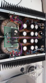
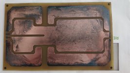
Ok, most things are sorted. For reference I'm going to attach a pic of an aleph-x I just build. It is dual mono but using crcc. It will give a visual example. I also attached a pic of the psu pcb's used (it is pretty old en dirty). This is pretty much the layout I would suggest.
look at a couple of things:
- pcb entry is on the left. You can see that there is only the psu lines coming from the rectifiers. They are separated not joined.
-The ground lines are kept separate until the end of the psu line. The last caps at the output. This would be the last caps of your supply on the right (top). (both in the schematic and the pics).
- Not visible but present. The output of the psu pcb on the right of the pcb gives options for grounding. there is one yellow wire going to the central star earth point. This is made with a bolt, nut and some wire lushes tying all grounds together at one single point (this is are just underneath the pcb's at the output in the pic). Connect the ground of the incoming ac inlet and psu trannie screens (yellow wire) there. I'd suggest using one of the bolts for fixing the ac psu inlet to the chassis.
- your pcb gives the hint of using an isolated cinch input. Use it and connect incoming signal directly to the pcb. Ground and positive signal wire. This is how i do it but the way AllenB described it is also valid. Uses an uninsulated chinch. Both ways are done commercially as well but most of the time you see the isolated version. I prefer that one personally and you can experiment with that
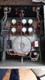
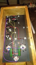
-Your pcb gives a connection for the loudspeaker return (ls return in the schematic). I would not use it but connect it to the psu ground out. like at the output of the pcb. You can change to the pcb ls return ground without risk. Try both. an extra pic is added showing a aleph-j. Hard to see but the speaker returns connect to the output of the psu.
- Hint twist ac carrying wires and those that carry large currents on dc.
Joris
Ok, most things are sorted. For reference I'm going to attach a pic of an aleph-x I just build. It is dual mono but using crcc. It will give a visual example. I also attached a pic of the psu pcb's used (it is pretty old en dirty). This is pretty much the layout I would suggest.
look at a couple of things:
- pcb entry is on the left. You can see that there is only the psu lines coming from the rectifiers. They are separated not joined.
-The ground lines are kept separate until the end of the psu line. The last caps at the output. This would be the last caps of your supply on the right (top). (both in the schematic and the pics).
- Not visible but present. The output of the psu pcb on the right of the pcb gives options for grounding. there is one yellow wire going to the central star earth point. This is made with a bolt, nut and some wire lushes tying all grounds together at one single point (this is are just underneath the pcb's at the output in the pic). Connect the ground of the incoming ac inlet and psu trannie screens (yellow wire) there. I'd suggest using one of the bolts for fixing the ac psu inlet to the chassis.
- your pcb gives the hint of using an isolated cinch input. Use it and connect incoming signal directly to the pcb. Ground and positive signal wire. This is how i do it but the way AllenB described it is also valid. Uses an uninsulated chinch. Both ways are done commercially as well but most of the time you see the isolated version. I prefer that one personally and you can experiment with that
-Your pcb gives a connection for the loudspeaker return (ls return in the schematic). I would not use it but connect it to the psu ground out. like at the output of the pcb. You can change to the pcb ls return ground without risk. Try both. an extra pic is added showing a aleph-j. Hard to see but the speaker returns connect to the output of the psu.
- Hint twist ac carrying wires and those that carry large currents on dc.
Joris
Attachments
Hello,
These 2.2 ohm will dissipate 3,3 watt with 1,5 A running through them. Of you still have the Lundahls better use the 1,7 ohm dcr from the ll2733 to get the necessay voltage drop.remember a crc is a 6db filter and a clc is a 12db filter. Find the information on the 50 watt amp from the French that explains why they changed from CRC to CLC for that power supply!
Of course LCRC with the right power transformer will be better but if you never try you will never know.
Lundahls states in their datasheets for power transformer that available output current for their transformers is 63% with capacitor input and 95% with choke input filter.
THIS has been so for ages . That is why some transformers mention their available output with choke input!
My guess is that using big caps will worsen things even more. The charging pulses will create lots of side effects. I used 2 or 3A rated diodes with a big transformer but no so high value caps but with choke input. It did not blow any fuses because the choke input will create a steady current charging the caps.All has been said.
Bye bye,Ed
Hello,
Better have the first caos not being 110000µF . Better have the right amount of µF to deliver enough current and rely upon the chokes to slow down the charging of the final caps. Using a suffiicient big enough cap which is smaller seize will alllow you to put it closer to the rectfiers which is good.
R core will not present a large inrush current like the big toriodals and EI cores do. Probably no need for the NTC .
Probably no need for the fuses right after the rectifiers. If one side will blow you will have dc at the output.
Bye bye,Ed
Hello,
I have had the original Hiraga built with 500va EI core using 68.000µF after the rectifier then a choke ( which they used in their 50 watt amp, i think dcr around 1 ohm ) then 2 330000µF caps on plus and minus side. It can be two things that cause a high inrush current: a huge amount of caps without any dcr during charging and the current that is needed to manetize the transformer core. R core having this current much lower compared to EI or big donuts.
Yes, the original poster started buying parts to quickly. 47000µF 63 or 40 volts will be big enough. Like the ones i posted a few weeks ago. One of my 68000µF did start leaking after a few years. The amp was on ALL the time but the French liked to use their caps close to the maximum rating combine that with large pulsating current all the time and one day it will go pop.
bye bye Ed
Hi Joris
For the moment I bought 5x2.2R and 2x0.1R to test the PSU, then I'll buy more for the second PSU.
I realise the caps are massive, if it makes it better I can certainly buy some lower capacitance ones for the first caps.
Lovely examples Joris of your amplifier build, I can see what you are talking about and it really helps to see this.
Hi AllenB
Yes i have bought 100w 10ohm&8ohm resistors (18 ohms) to load the PSU. I do own a handheld oscilloscope. I don't have a variac, i was thinking maybe of buying one.
Variac (Variable Autotransformer) - 240V 1A Surface Mount - Carroll & Meynell | eBay
3 Amp Variac Variable Transformer 500VA Max 0-240 AC Volt Output regulator New | eBay
Hello,
Better have the first caos not being 110000µF . Better have the right amount of µF to deliver enough current and rely upon the chokes to slow down the charging of the final caps. Using a suffiicient big enough cap which is smaller seize will alllow you to put it closer to the rectfiers which is good.
R core will not present a large inrush current like the big toriodals and EI cores do. Probably no need for the NTC .
Probably no need for the fuses right after the rectifiers. If one side will blow you will have dc at the output.
Bye bye,Ed
This is why Joris has put resistors after the rectifiers? And i also thought that's why we are using r core transformers because they wont cause a massive inrush of current like other transformers.
I will still add fuses for that peace of mind and extra protection! I also refer to Daniels 30w Hiraga build who has twice as much capacitance as his first caps, where as my PSU will have resistors and a choke. So i am hoping this will suffice! But like you said you have to try and see otherwise you will never know!
Hi Vishalk,
Ok, now i understand. Was worried a bit about the numbers but this is fine. Tough i agree with Eduard on the value of that first cap we've already taken measures to control the charge pulses on that first cap with the ,1r resistors.
It's up to you but i would like to see you get it working before buying more components. We are probably going to run in to some issues along the way and i want to minimise the risk at unneeded cost.
Once everything is up and running we can go and look at optimising and tuning components. However it would be a nice learning excercise to try and find a lower capacitance but good enough first cap. For that you would need to get back to psu designer.
The trick there would be to look at the max current going in to the second cap. You would want the lowest value capacitance that has a slightly higher ripple current rating. That way it will be able to supply the needed current to the second cap. luckily you have those nice chokes. They will lower the needed current.
This is the reason Eduard and Pieter where pushing for a choke input as well. A choke is in itself an energy storage and regulates current. For fun simulate a crc and a lcrc psu. Then look at the ripple voltage and current at the first cap. the crc will show a sawtooth pattern while the lcrc will show a sinewave pattern in the voltage and current will show lower peak values. the latter is much smoother. Here smooth is better.
So after you have got everything up and running enjoy the amp and start saving for two extra chokes in the future.")
Joris
owh you wher posting while i was writing. guess some of it was already cleared up
Ok, now i understand. Was worried a bit about the numbers but this is fine. Tough i agree with Eduard on the value of that first cap we've already taken measures to control the charge pulses on that first cap with the ,1r resistors.
It's up to you but i would like to see you get it working before buying more components. We are probably going to run in to some issues along the way and i want to minimise the risk at unneeded cost.
Once everything is up and running we can go and look at optimising and tuning components. However it would be a nice learning excercise to try and find a lower capacitance but good enough first cap. For that you would need to get back to psu designer.
The trick there would be to look at the max current going in to the second cap. You would want the lowest value capacitance that has a slightly higher ripple current rating. That way it will be able to supply the needed current to the second cap. luckily you have those nice chokes. They will lower the needed current.
This is the reason Eduard and Pieter where pushing for a choke input as well. A choke is in itself an energy storage and regulates current. For fun simulate a crc and a lcrc psu. Then look at the ripple voltage and current at the first cap. the crc will show a sawtooth pattern while the lcrc will show a sinewave pattern in the voltage and current will show lower peak values. the latter is much smoother. Here smooth is better.
So after you have got everything up and running enjoy the amp and start saving for two extra chokes in the future.
Joris
owh you wher posting while i was writing. guess some of it was already cleared up
Last edited:
Hi Vishalk,
A Variac would be nice but the light bulb limiter will suffice. The Variac is a good investment in the long run but not strictly needed now. I would rather see you saving the money for those extra chokes
It's very good news to me that you have a scope. That with a couple of multimeaters will do very nice. Indeed you have the load for testing and you can re use it for testing the amp afterwards. .
Hello,
Read this link please
RR#002 - DC Filament Supply Test
Now read it one more time! lol
Using a to big capacitor after the rectifier makes things worse. All negative side effects of the rectifiers are magnified once that cap is to big.
With 24 volt transformers you can also use choke input with the ll2733 if you add a seperate power supply for the input stage i think. Reducing bias current could be necessary if the power transistors are mounted close to each other.
The Hiraga amp has a potentiometer to control dc at the output. If pos and neg side of the power supply are not equal you can compensate that with turning that meter. If one of the fuses blow for whatever reason you probably fry your speaker. But you have double mono so only one side.
Wth a 500 VA variac you can gradually move up the value of the voltage on the caps which is good if they have not been used for long time. Give each channel its own power switch. Switching on two 500VA rcore without choke input could be to much.
Try to find two 2*36 volts R core 300VA or more. Usually 24 volts is more common.
bye bye,Ed
Hi Eduard,
Nice link. I sent Vishalk a pm asking him for an email adress. Made a copy of Allen Wright's pages in the pre amp cookbook on psu's. I expect you might know it. Gives a very good explanation about the reason for using a choke input. I'd like to send it to Vishalk.
I have not looked in to it at detail but his pcb kit comes with adjustable kubota regulators for the input stage. I have no personal experience with those but they could be adjusted to someting like 16 ~ 17 V dc approximatley. That would work. The ccs load might need some work though.
True about the fuses in the psu lines regarding possible failure in actual operation. For now i think they are usefull during testing and afterwards we can discard them. I never use u fuse after the psu myself.
Joris
trying to find r core transformers is hard Eduard, to source them and to get the made is difficult, i wish it wasn't, i can get EI and Torodial all day long.
Hopefully when everything is connected, even the lundhals in common mode, i will see 28v, the amplifier boards can work between 24v to 30 plus volts. So hopefully i wont need a seperate power supply for the input stage?
I intend to use a speaker protection module, i could even add a soft start which connects to both transformers?
Ill get the psu built and report back the results, as Joris said, build it and test it then we can go from there.
https://www.lundahltransformers.com/wp-content/uploads/datasheets/1694.pdf
These ll1694 chokes can handle 3A in parallel, i have a buyer for my ll2733 chokes who will give me what i paid for them.
The ll1694 are cheaper and if i buy four i can get a discount!
Now i am happy to keep the ll2733 and use them in common mode, but ultimately i need four chokes? But then i assume the voltage drop would be greater across 4 chokes so i would need more then 24vac from the transformer?
Still trying to figure out PSUD!
Hello ,
KEEP the ll2733 the higher mH is better and they can take 1,7A . If you are putting the two coils of the LL1694 you will get even lower mH and how are you going to make a common mode connection??
500 VA transformer with the right choke input and you will not need a soft start. Why make things so complicated.
MAKE a test set up and see how much output voltage you will get when you use the LL2733 in common mode connection. Feeding the output stage with 20 volts will work too( you will get lower power output) But you might need more to feed the kubota boards than 20 volts. You could reduce the bias current at the output stage a little bit to limit voltage drop across the ll2733
A 20 watt amp with choke input will sound more powerful than a 30 watt with conventional power supply.
I will be gone for a few weeks. No use keep repeating myself.
Bye bye , Ed
- Home
- Amplifiers
- Power Supplies
- 30w Jean Hiraga Power Supply Design, one large capacitor or several?