I am trying to understand why nearly every circuit I see for a SE 300B amplifier shows no coupling capacitor between the plate of the first stage and the grid of the second stage. My suspicion is that it works to provide a DC offset that will change with the current draw of the first stage but I could be wrong. Either way I just want a better understanding of what is going on. Thanks in advance for any help!
Attachments
Excellent, just having the proper name should help me to research and understand this. Thanks leadbelly!
FYI - Direct coupling is desirable as it eliminates one of the more sonically influential parts in the signal chain - the coupling capacitor. As you've noticed, people go out of their minds over capacitors, with prices on the 'best' parts approaching those of fine scotch.
But the best sounding capacitor is no capacitor at all - hence direct coupling. If you can dispense with the part, you can dispense with the artifact as well.
It's not quite that simple. You are obliged to use a cathode bypass cap on the driver stage, since you have quite a large resistor. One alternative is filament bias on both input and driver stages, using a coupling cap. Here you have eliminated the cathode bypass cap on the driver stage at the expense of a small cap like 0.1uF or 0.2uF which can be a really good cap like teflon. I use a Russian FT-2 here which is boutique quality at Soviet surplus prices. It's my preferred solution, but you need to use tubes like 01A, 26, 4P1L. But I'd be using those tubes anyway so that's perfect.
It's not quite that simple.
"If you can dispense with the part, you can dispense with the artifact as well."
In this case, that may well be - but it doesn't counter the motivation behind direct coupling. There are plenty of other cases where directly coupled stages are implemented without introducing great honking electrolytic cathode bypass.
Direct coupling is useful when it is appropriate. I can't see the point of eliminating a harmless film coupling cap and introducing a large electrolytic instead. One could argue that the stage is still AC coupled for AC, but via a worse cap than the normal circuit. Bias problems in the first stage will also be exported to the second stage. Blocking is not entirely eliminated, the bias shift due to excess signal just happens at the cathode instead of the grid.
What DF96 said. It's much harder to find large value capacitors whether film or electrolytic that can match the performance of a small film cap in the grid circuit.
There is another problem with this design and that is it's asymmetrical swing. The maximum positive amplitude voltage swing on the driver tube is somewhat marginal, of course there may be some intent to cancel 2nd harmonic distortion which IMVLE is questionable. I prefer a linear driver stage and to just live with the distortion generated in the output section.
If already built I'd roughly double the plate current in the 2nd stage stage and shift the operating point enough to allow for at least 200Vpp linear swing in the driver. (Plate and cathode resistor value changes are all that are required.)
If you haven't built this thing and this is more than a just a technical question I would recommend you check out the Tubelab SE instead. It's a much better design IMO.
Using just 1 part gets us closer to the music:
A front row ticket to a live un-amplified concert.
I have built amplifiers that are DC coupled, interstage coupled, RC coupled, fixed bias, self bias, battery bias, output transformer, OTL, single ended, push pull, etc. And each one has a tradeoff or two. But they can each be designed well, and as such they provide hours of enjoyment, both in designing, building, and especially during the listening sessions.
But nothing is really the same as un-amplified live music.
Oh yes, I did not forget one of the earliest attempts at settling that discussion.
In the late 50s or early 60s, Acoustic Research rented a concert hall, microphones,
and recorder. They used their Acoustic Research speakers and a Dynaco amplifier.
They had a string quartet play and recorded it.
Then they opened the concert hall for a comparison session, alternating between live and recorded music. The players always moved their bows, etc. in order to make it harder to tell the difference between live and recorded playback.
Stereos sound great. Just don't forget to go hear live un-amplified music once in a while.
I just tested the same driver circuit for my 2A3 and 300B SE amp. I found that the cathode resistor for the first amplification stage need to be tuned to get even clip for the final output. Most likely the drive of the second stage is not large enough to push the power tube for its maximum output.
Also, the cathode bypass capacitor has significant impact on the sound character. I tried both film and electrolytic one. I prefer electrolytic as it sound more natural to me.
Johnny
Also, the cathode bypass capacitor has significant impact on the sound character. I tried both film and electrolytic one. I prefer electrolytic as it sound more natural to me.
Johnny
If the coupling capacitor was there you would still need to bias the grid to 90v.
This would need two resistors.
So its much better to direct couple and lose 3 components.
The second stage is a phase splitter hence the 90v bias on the input to give 90v on lower resistor to centralise its swing.
This would need two resistors.
So its much better to direct couple and lose 3 components.
The second stage is a phase splitter hence the 90v bias on the input to give 90v on lower resistor to centralise its swing.
If already built I'd roughly double the plate current in the 2nd stage stage and shift the operating point enough to allow for at least 200Vpp linear swing in the driver. (Plate and cathode resistor value changes are all that are required.)
If you haven't built this thing and this is more than a just a technical question I would recommend you check out the Tubelab SE instead. It's a much better design IMO.
I looked at the Tubelab SE but I'm really trying to avoid the use of semiconductors and ICs, going for an old school thing. Sure, I know that this means I will sacrifice some sound quality and money. I will investigate the suggestions you made for the second stage, should be able to figure that out.
Thanks everyone for your feedback, it is much appreciated!
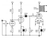
I am trying to understand why nearly every circuit I see for a SE 300B amplifier shows no coupling capacitor between the plate of the first stage and the grid of the second stage. My suspicion is that it works to provide a DC offset that will change with the current draw of the first stage but I could be wrong. Either way I just want a better understanding of what is going on. Thanks in advance for any help!
It has nothing to do with DC offset, at least not for the schemo shown. There are other reasons for the DC coupling. If including gNFB, eliminating one RC coupling helps improve the phase margin at low frequencies. Even if you don't include gNFB, it's still desirable. Each RC coupling is a HPF. If you don't stagger the time constants properly, you lose too much from the low end. Staggering time constants can lead to very large values for the interstage coupling capacitor.
Why?nigelwright7557 said:If the coupling capacitor was there you would still need to bias the grid to 90v.
No it isn't. This is an SE design.The second stage is a phase splitter
Only at the very lowest frequencies. At intermediate frequencies (audio LF and subsonic) you will still get significant phase shft in the region where the cathode electrolytic has an impedance between the cathode resistor value and 1/transconductance. This is likely to be the region where the OPT has a phase shift and other AC coupling too.Miles Prower said:If including gNFB, eliminating one RC coupling helps improve the phase margin at low frequencies.
This direct coupling swaps a rolloff for a very deep shelf. Near the higher corner frequency these will look very similar in phase and amplitude terms.
FYI - Direct coupling is desirable as it eliminates one of the more sonically influential parts in the signal chain - the coupling capacitor.
...before the output tube that works on it's edge, hence the cap sees non-linear load resistance.
In an SE amp the most sonically influential part is the decision to use SE. Next comes the OPT. Then the valves and their bias points. After them are any electrolytics caps, followed by film caps. Finally bringing up the rear are the resistors.legendre said:FYI - Direct coupling is desirable as it eliminates one of the more sonically influential parts in the signal chain - the coupling capacitor. As you've noticed, people go out of their minds over capacitors, with prices on the 'best' parts approaching those of fine scotch.
Hence coupling caps are the second least influential parts. People certainly "go out of their minds over capacitors"; why concentrate on one of the least important things?
Anyway, this design seems to replace a harmless cap (second stage grid) with an almost harmless cap (second stage cathode) yet leaves another cap being misused to drive the output stage.
Why is it being misused?
- Status
- This old topic is closed. If you want to reopen this topic, contact a moderator using the "Report Post" button.
- Home
- Amplifiers
- Tubes / Valves
- 300B SE Driver Stage Understanding