what is the question ?
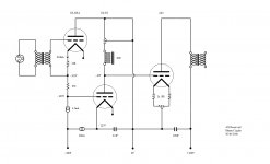
My concern is to do with the input capacities (there are more than two) wrt the input transformer, and also the 'long tail' of the driver tube - wrt bias shift (signal goes high and Ip wants to increase but is held constant as so the effect on grid bias voltage) and the implications therein - and the problem could be that the change in bias appears in the plate circuit along with the input signal and it creates a low frequency signal that isn’t present in the input signal.
LH/S
Last edited:
"Why?" would be my question.petertub said:what is the question ?
The input stage is not a follower.soulmerchant said:What's the gain on the input follower stage?
..
3 stage DC - any thoughts?
..
LH/S
Seeing your schematic, I thought you might be interested in the links below.
Darius' Loftin-White website
Sheldon's L-W 801 thread
diyAudio thread on Darius' L-W
"Why?" would be my question.
Which is kind of what I was suggesting..
The input stage is not a follower.
Correct. But still no answer from the original poster.
You need to consider what happens on power up when all tubes are cold. They will all warm up at different rates which could leave the 2A3 at zero bias as the others warm up. My limited experience with 2A3's is that they are rather slow though.
This is a good point, but my assumption was that they would use damper diodes to rectify the B+ and SS to rectify the negative rail.
All the same... separate filament bias for 2 stages (why not 3 while you're at it?) + input transformer and a plate choke... all for each channel...plus separate +/- rails.. no thanks.
For nearly a year now I've been running a cascoded CCS on a triode strapped pentode direct coupled to 2a3 (or 45/46).
Before that I tried darius' bootstrapped L-W using 6sl7, then did it with a mosfet, then tried mosfet follower similar to how you (Tubelab) suggest. Readers please visualize a most respectful tip of the hat!
")
But I had some interesting little pentodes in my stash, so tried cascaded CCS triode strapped pentode with mosfet follower. Now THIS was good... and there are a LOT of great cheap pentodes to try out there... but after a while I figured what the heck, the impedance is not so high so I threw away the mosfet follower.
Of course the original poster might also be enamoured with DHT's, filament bias and iron. I can only speculate.
Ian
Last edited:
I have heard a variant of this amp, and if nothing else it sounded pretty good, but it is a complex solution in order to avoid most capacitors in the signal path, and make no mistake XuF is important and right in the audio signal path.
My fear is what happens in the event of a tube failure, the end result may not be pleasant.
It is a (distant?) variant on Jack Elliano's reactance drive design idea which on the face of it is much simpler if lacking the charm of dhts everywhere.
My fear is what happens in the event of a tube failure, the end result may not be pleasant.
It is a (distant?) variant on Jack Elliano's reactance drive design idea which on the face of it is much simpler if lacking the charm of dhts everywhere.
Hi Kevin
The inherent risk of catastrophic failure can in a way be managed with some well placed fuses. At least that is what I have been doing with my L-W's so far.
After mulling over this design I must admit that the un-balancer approach makes it something I kind of want to build. But I don't really have a balanced source so its a kind of pointless.
Ian
I always look at fuses as protection of last resort, IMVLE they usually blow after the damage is done and before the fire starts.. LOL
And without a modicum of self bias in the 2A3 there is really no way to protect against things like open filaments in the other DHTs which is not an uncommon failure mode. (It has happened to me) Fuses probably are the only option here to protect against a failure in the driver tube.
You can drive the input transformer unbalanced, while not optimum it should work fine.
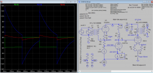
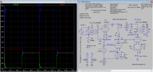
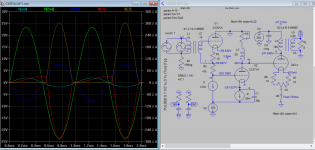
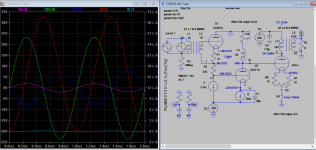
Here are some of simulations I done and would like to share with you. The 1st and 2nd has max gain of 8 and 3 respectively, and it appears 2V is required for full output. It also appears that 2nd stage is more restricted in the bottom end freq response than the 1st stage (as shown by square wave response). Xuf is determined by the best bottom end freq. response but I don't know actually how it's determined. If bias is zero on the output stage it will draw few hundred mA of current, so I think too a fuse is required to protect the OT.
Attachments
Last edited:
Hi,
soulmerchant, input stage gain is full mu of the tube. As to 2A3 being easy to drive, thats great and also nothing to stop using a more -ve supply and using 300B output stage at 350Vp-k ~75mA.
kevinkr, a relay with 24V coil which sets up at 20mA (1100 DCR are common enough) can easily be placed in series with the driver tube plate circuit, contacts could switch the primary of the OP stage B supply - input and driver set up first, output comes up last, and its fail safe. Consider; input tube fails and driver grid goes low, zero plate current in driver = no voltage drop across relay coil and B supply to OP stage drops out. If driver tube fails then B supply to the OP stage drops out altogether. If output stage drops out, no problem.
I'd be interested to learn more about the similar circuit which you have experience with - this one here sets the grid bias to the driver tube correctly and regardless of 'tube to tube' variation of the input tube itself and compensates for it as it ages/drifts in Vp-k for the fixed value of Ip. I haven't seen that anywhere before.
Of course, X.uf or any other final filter element is going to be always 100% included in the AC signal loop.
Koonw, Thank you !!. I'd like to follow with you a little more in how the circuit is entered into your simulations. What is the bias to the input stage as you have it?.. with 254mA through 18R should be -4.5V and with 3.5mA fixed Ip, voltage across the tube should be very close to 100VDC. Output stage plate current should be double the 27mA figure for 250 Vp-k and -45V ? (if I read the sim. correctly). Also, the way that the XuF is drawn as bypass cap across the tube would require first the cap to charge before the cct will stabilize, but a small issue.
I'd really like to learn how to use this simulator which you have, but for now which parameters did you enter regarding the input transformer. Assume 1:1 is fine, how many variations on capacitance does it allow for with a transformer model like this?.. and on that note is there a product/graph available for the input stage frequency response?. Very much thank you, and again.
And thanks to all but still none of this addresses my main concerns as outlined in post #3.
LH/S
Last edited:
Hi Kevin
Indeed, open filament on the 2a3 is far more common than most would imagine. And I for one would most prefer to spare my driver circuit.
I've been using a 20mA fuse on the driver. The CCCS is well sinked, so is unlikely to fail before the fuse goes, but if you put an appropriate shunt in parallel with the whole input/driver, the circuit will definitely blow the fuse if B+ rises beyond tolerance.
Ian
"Koonw, Thank you !!. I'd like to follow with you a little more in how the circuit is entered into your simulations. What is the bias to the input stage as you have it?.. with 254mA through 18R should be -4.5V and with 3.5mA fixed Ip, voltage across the tube should be very close to 100VDC."
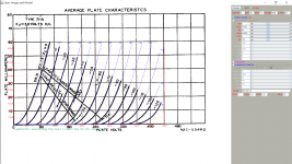
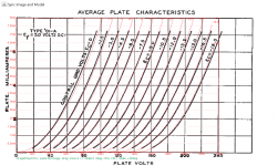
Yes, you're correct. with 18R the tube is under biased (only < 0.2V) and working in Class A2!. I re-bias it so the voltage across the 1st tube is about 100V, it's now in Class A1 now, distortion went down by 0.2% from 1.2%. The original datasheet where the models are derived are also attached.
Yes, you're correct. with 18R the tube is under biased (only < 0.2V) and working in Class A2!. I re-bias it so the voltage across the 1st tube is about 100V, it's now in Class A1 now, distortion went down by 0.2% from 1.2%. The original datasheet where the models are derived are also attached.
Attachments
Last edited:
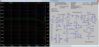
http://www.jensen-transformers.com/wp-content/uploads/2014/08/jt-112p-2hpc.pdf
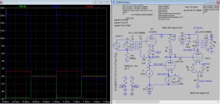
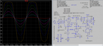
The above line input transformer can handle low freq down to 1 Hz. There is no obvious DC offset from 1st and 2nd stage as seen from SIM plot which could be added to signal you mentioned in #3, it must be confirmed by actually building the model.
The above line input transformer can handle low freq down to 1 Hz. There is no obvious DC offset from 1st and 2nd stage as seen from SIM plot which could be added to signal you mentioned in #3, it must be confirmed by actually building the model.
"Koonw, Thank you !!. I'd like to follow with you a little more in how the circuit is entered into your simulations. What is the bias to the input stage as you have it?.. with 254mA through 18R should be -4.5V and with 3.5mA fixed Ip, voltage across the tube should be very close to 100VDC."
Yes, you're correct. with 18R the tube is under biased (only < 0.2V) and working in Class A2!. I re-bias it so the voltage across the 1st tube is about 100V, it's now in Class A1 now, distortion went down by 0.2% from 1.2%. The original datasheet where the models are derived are also attached.
Koonw, I will send PM and would like to further discuss. Thank you for staying relevant and for being helpful.
LH/S
Last edited:
http://www.jensen-transformers.com/wp-content/uploads/2014/08/jt-112p-2hpc.pdf
The above line input transformer can handle low freq down to 1 Hz. There is no obvious DC offset from 1st and 2nd stage as seen from SIM plot which could be added to signal you mentioned in #3, it must be confirmed by actually building the model.
I was thinking it had to do more with the capacitance (all three+) of the transformer itself, and that high-ish Lpri (which the drive to the amplifier would ideally like) was at odds with the interwinding C (all), so to find a 1:1 tx with decent primary inductance, yet through winding technique manages to reduce capacitance - http://www.lundahl.se/wp-content/uploads/datasheets/1570_0xl.pdf
?
LH/S
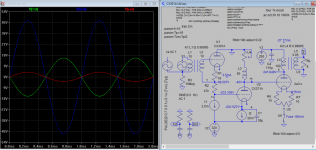
I just thought you can look into DC offset along with AC at various points for clues and see if the level of offset is within tolerance or not, esp. 2nd harmonic distortion which can create quite significant level of dc offset. It may be then possible to find the source of additional distortions if any by reducing or increase the capacitance and other parameter of the input transformer or other components.
.four 1k v(2)
.four 1k v(3)
.four 1k v(5)
.step param Level list 0.1 0.5 1 1.5 2 3 5
where Level is the input level.
Attached is the log file containing the distortion and DC offset.
.four 1k v(2)
.four 1k v(3)
.four 1k v(5)
.step param Level list 0.1 0.5 1 1.5 2 3 5
where Level is the input level.
Attached is the log file containing the distortion and DC offset.
Attachments
- Status
- This old topic is closed. If you want to reopen this topic, contact a moderator using the "Report Post" button.
- Home
- Amplifiers
- Tubes / Valves
- 3 stage DC - any thoughts?