The LT1084 is not a real LDO, it has 1V drop.
A better choice is the LT1581: LT1581 - 10A, Very Low Dropout Regulator - Linear Technology
It will be under 0.3V, and is good for 10A which means you can also get rid of the 0.22 ohm.
You could do better with a discrete regulator, but it would have to be MOS-based.
If you combine this VR with schottky diodes, or the synchronous rectifier, you should be OK
The LT1581 started to look good until I got to the part of the data sheet "Absolute Maximum Ratings" Vpower Input is only 6V. Funny that on page 5 of the data sheet it says ""Vpower pin is limited to 7V". So..it mightwork but I'd have to clamp the input voltage. I don't think this one is the way to go here.
Sorry about that, I missed the "details".The LT1581 started to look good until I got to the part of the data sheet "Absolute Maximum Ratings" Vpower Input is only 6V. Funny that on page 5 of the data sheet it says ""Vpower pin is limited to 7V". So..it mightwork but I'd have to clamp the input voltage. I don't think this one is the way to go here.
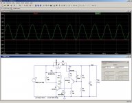
Another option is a discrete, MOS-based regulator like this example.
It will regulate with just 0.1V @3.5A and is not input limited.
If ground polarity isn't an issue, you can build it with the opposite polarity and benefit from a much wider choice of MOS transistors.
Here, the reference is a standard red LED dropping 1.8V @5mA.
It also compensates for transistor's Vbe.
The exact voltage can be adjusted by making one of the resistors variable.
Attachments
I did the math for the 0.22 ohm resistors that summed the paralleled regulator outputs that I had intended and realized that there is quite a voltage drop there at such a high current so that had to go. I've ordered an LT1083 (7.5A adjustable). The LT1083 should just barely fit between the fins of my heat sink. I also ordered some of the MBR735G Schottky diodes. I had never before noticed rectifier diodes paralleled to lower the voltage drop as in Elvee's schematic.
Thanks everyone for the encouragement.
Thanks everyone for the encouragement.
I have the circuit working well now. I replaced the bridge rectifier diodes with paralleled MBR735G to lower the voltage drop. I increased the capacitance in the raw supply to 57,000 uF to reduce the ripple. I replaced the paralleled 5A adjustable voltage regulators with a single 7.5 A three pin regulator (the LT1083CP) to eliminate the 0.22 Ohm summing resistors. The leads of the LT 1083CP required a lot of filing to get them to fit into the holes on the circuit board. Now I have 6.3 Volts at 3.7 Amps for my filament supply. My measurements show that it will stay in regulation until the primary AC voltage gets below 113.6 Volts. That should be just enough to get by with since my home usually has 120 Volts. I have an auto-transformer so I could find out where it drops out. Immediately above the drop out point I measured the raw supply voltage. I got 7.64 Volts DC and on top of that was 0.36 Volts of AC ripple.
Thanks for the feedback here. I'm supplying filament voltage for the output stage of a DAC. The tubes I chose (4) required about twice more current than I expected (I should have looked at the data sheet). With another small dual triode to light It all required 3.7 Amps. The voltage regulator doesn't even get very hot to the touch so It should be fine.
Thanks for the feedback here. I'm supplying filament voltage for the output stage of a DAC. The tubes I chose (4) required about twice more current than I expected (I should have looked at the data sheet). With another small dual triode to light It all required 3.7 Amps. The voltage regulator doesn't even get very hot to the touch so It should be fine.
- Status
- This old topic is closed. If you want to reopen this topic, contact a moderator using the "Report Post" button.