Yes, there are a bunch that one could buy of course... I would like to see a community effort to create those small 3-pin cards in a variety of the common voltages working at common currents. Maybe an excel sheet to do the maths.
Life is to short for everyone to reinvent everything and the purse is to shallow for paying 25-30€ a piece for these. Could we gather around a good design and keep the design updated and freely available as a schema, gerber and pdf.
If designs with sense wires are prefered - lets go for one of them. The people offering readybuilt circuits are most welcome to contribute as this call is about the design, files and pdf's for the diyers. I have gathered some designs that have been posted in a multitude of threads and they are finding their way into eagle. With proper credits to the posters these designs will be added here as (eagle) shemas, gerbers and pdf's. I hope others will heed the call and add designs as this site is by fanatics for fanatics
Regards
Last edited:
Hi Turbon,
I have been looking at some 4 legged devices with lo drop out for powering a dacs and maybe some digital circuits in the DCX and DEQ,I am making separated A and D, PS for fast quiet supplies.
I have also thought if you use a LM317 to supply power to a 9,5,3.3 v fixed 3 legged regulator could you obtain the same results?
happy Listening,
NS
For digital I would use LDO devices for low current (SMPS laid out properly for larger current demands) on board as near as the point of load as possible all SMD devices and caps, I would also use pi filters with a ferrite on the inputs to create a small power island. This is the best way to do this and tailor the POL supply design to the circuit being done so you minimise the copper plane are for the voltages.
The supply voltage wants to be commensurate with the output voltage, i.e. not dropping to many volts to get the desired OP voltage (use 3V3 in for 1.2V 1.8V etc.).
You can also vary the device depending on the current requirements.
The supply voltage wants to be commensurate with the output voltage, i.e. not dropping to many volts to get the desired OP voltage (use 3V3 in for 1.2V 1.8V etc.).
You can also vary the device depending on the current requirements.
the original big dac from quangho used lm317 in it's power supply,worked well,I also have them in several dac's from across the pond.
I will build some ldo's just for digital,Kinda on the fence about using smps or linear for analog.
I built the opus all digital,LDO's and smpts sounds good,,,,used Lm317 for analog opamp power,
NS
I will build some ldo's just for digital,Kinda on the fence about using smps or linear for analog.
I built the opus all digital,LDO's and smpts sounds good,,,,used Lm317 for analog opamp power,
NS
I remembered wrong, the subbu dac uses a lm723.
The schema for a LT1431 is now drawn in Eagle and passed without errors. It is designed by 1audio (Demian Martin) and shown amongst the Audiowidget topics and Asynchronous I2S FIFO posts. Borge uses it in the new Henry Audio 128 mkII dac. So if Demian doesn't mind I would like to pass the files for the community to use (when laid out on board ). Demian also had ideas of improvement by adding inductors or ferrite beads that I would like to add.
Regards
The schema for a LT1431 is now drawn in Eagle and passed without errors. It is designed by 1audio (Demian Martin) and shown amongst the Audiowidget topics and Asynchronous I2S FIFO posts. Borge uses it in the new Henry Audio 128 mkII dac. So if Demian doesn't mind I would like to pass the files for the community to use (when laid out on board
). Demian also had ideas of improvement by adding inductors or ferrite beads that I would like to add.Regards
Last edited:
NS!
LM317 doesn't look to bad comparing to ultranew devices. Please come forth with design ideas and schemas. Jean-Pauls lm723 doesn't look bad either but it would be hard to implement on a small footprint. Otherwise I have adm7150, adp151, lp2992 and tps7a47 so far. As I have started with the lt1431 I will complete it before starting another one. Please if you consider it worthwhile - add an 1.2V LDO shematic at least if not the whole package in Eagle. This task forced me to learn a lot about Eagle. If only a schematic I won't mind put it into Eagle and create the package. Of course everything we create needs scrutinizing before one starts to mix chemicals or send it to a shop .
Also ask yourself - is this for digital, clock or analog?
Regards
LM317 doesn't look to bad comparing to ultranew devices. Please come forth with design ideas and schemas. Jean-Pauls lm723 doesn't look bad either but it would be hard to implement on a small footprint. Otherwise I have adm7150, adp151, lp2992 and tps7a47 so far. As I have started with the lt1431 I will complete it before starting another one. Please if you consider it worthwhile - add an 1.2V LDO shematic at least if not the whole package in Eagle. This task forced me to learn a lot about Eagle
. If only a schematic I won't mind put it into Eagle and create the package. Of course everything we create needs scrutinizing before one starts to mix chemicals or send it to a shop .Also ask yourself - is this for digital, clock or analog?
Regards
Last edited:
The following circuit presented to many has been adapted by Henry Audio in his -
Henry Audio USB DAC 128 [FONT=Verdana,Italic]mkII. An amazing top of the edge product without secrets - it's all open.[/FONT]
[FONT=Verdana,Italic][/FONT]
[FONT=Verdana,Italic]
[FONT=Verdana,Italic][/FONT]
[FONT=Verdana,Italic]Remember and as you can see - this is for the digital domain. There are other parts feeding this that has to be taken into consideration - look at the whole schema to better a simple three legged variant.[/FONT]
Regards[FONT=Verdana,Italic]
[/FONT]
Henry Audio USB DAC 128 [FONT=Verdana,Italic]mkII. An amazing top of the edge product without secrets - it's all open.[/FONT]
[FONT=Verdana,Italic][/FONT]
[FONT=Verdana,Italic]
An externally hosted image should be here but it was not working when we last tested it.
[/FONT][FONT=Verdana,Italic][/FONT]
[FONT=Verdana,Italic]Remember and as you can see - this is for the digital domain. There are other parts feeding this that has to be taken into consideration - look at the whole schema to better a simple three legged variant.[/FONT]
Regards[FONT=Verdana,Italic]
[/FONT]
Right, an LT1431 as a starter...
This one is for 3.3V. Vin >= 5V. Give it another volt and it gives better measurements I have read
Now where is that PI filter for the input
Not quite done yet. I need help on Eagle on the following topics:
1. When is enough fiddling enough?
2. I have changed the Prefixes on parts to IC for the LT1431 and Q for the transistors but it doesn't seem to change in schema or layout. What did I miss?
3. The Prefix and number should be enough. The Name clutters it all doesn't it?
4. How do one create a groundplane?
5. DRC complains about Drill size for the vias... Where do I fix this?
I would be happy to get feedback on the layout as is. The board is now about 50*20mm
Pics, yes pics keeps me quiet
Regards
This one is for 3.3V. Vin >= 5V. Give it another volt and it gives better measurements I have read
Now where is that PI filter for the input
Not quite done yet. I need help on Eagle on the following topics:
1. When is enough fiddling enough?
2. I have changed the Prefixes on parts to IC for the LT1431 and Q for the transistors but it doesn't seem to change in schema or layout. What did I miss?
3. The Prefix and number should be enough. The Name clutters it all doesn't it?
4. How do one create a groundplane?
5. DRC complains about Drill size for the vias... Where do I fix this?
I would be happy to get feedback on the layout as is. The board is now about 50*20mm
Pics, yes pics keeps me quiet
An externally hosted image should be here but it was not working when we last tested it.
An externally hosted image should be here but it was not working when we last tested it.
Regards
Last edited:
For digital I would use LDO devices for low current (SMPS laid out properly for larger current demands) on board as near as the point of load as possible all SMD devices and caps, I would also use pi filters with a ferrite on the inputs to create a small power island. This is the best way to do this and tailor the POL supply design to the circuit being done so you minimise the copper plane are for the voltages.
The supply voltage wants to be commensurate with the output voltage, i.e. not dropping to many volts to get the desired OP voltage (use 3V3 in for 1.2V 1.8V etc.).
You can also vary the device depending on the current requirements.
Thanks marce
Do you have a schema that shows how you would prefer it to look like?Regards
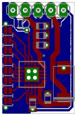
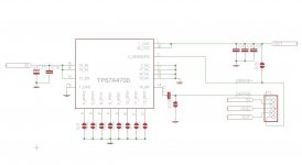
Does this 3pin regulator need to be designed in such way that anyone can solder it himself? If not, I can share my TPS7A4700 3pin design, to spare you some time....
BTW this PCB is replacement for LM78xx devices and has sensing pins (if not used, they can be bridged).
Best Regards,
Aleš
BTW this PCB is replacement for LM78xx devices and has sensing pins (if not used, they can be bridged).
Best Regards,
Aleš
Attachments
Now Aleš.
This is the second week of my Eagle journey. Can it be doublesided?
Still no answers on ground planes as I want on my regulators but initially I can live without them until v0.9 of my layouts.
I'll put it in and create the device as it isn't in the Eagle libraries. But it will take some weeks as the LT1431 is first in queue.
Regards
Last edited:
Wow, I'll have to look at it another time again
Thanks Aleš
Does this 3pin regulator need to be designed in such way that anyone can solder it himself? If not, I can share my TPS7A4700 3pin design, to spare you some time....
BTW this PCB is replacement for LM78xx devices and has sensing pins (if not used, they can be bridged).
Best Regards,
Aleš
Have you had complaints about some part was tough or impossible? Yes, the parts are small and one needs aids soldering such parts. If that is the reason then whatever I do the parts stays small as before... But still Aleš, would you accept that I'll copy your design and share it? Sorry, you already accepted. If anyone doesn't work faster than me I'll put a first version up in a feew weeks. I really need a good 1.2V 3-pin reg after the 3.3V one
Regards
Last edited:
- Status
- This old topic is closed. If you want to reopen this topic, contact a moderator using the "Report Post" button.
- Home
- Amplifiers
- Power Supplies
- 3-pin PSU's for 1.2V, 3.3V and 5V?