C=19.8125? That would make D=6.3". Does the TD125 use a subplatter?
You need to factor in belt thickness as well to get close:
MRPM/33.333=(Platter dia +.5t)/(Pulley dia +.5t)
Where MRPM= Motor RPM, t= belt thickness.
For 33.333 RPM, MRPM=300 RPM and belt thickness=0.080", the pulley would be 0.664".
You need to factor in belt thickness as well to get close:
MRPM/33.333=(Platter dia +.5t)/(Pulley dia +.5t)
Where MRPM= Motor RPM, t= belt thickness.
For 33.333 RPM, MRPM=300 RPM and belt thickness=0.080", the pulley would be 0.664".
Shoot I was hoping to get a response in first, beat me to it. Yes I'm an idiot I was using circumference for the calculations and reading pulley diameter. And the belt is a bigger factor than I realized.
Better question is there an ideal rpm range for the BLWS? Will need to do 33 and 45, general min/max is great too. See if I can get close enough with something stock or if I'll need to look into making one. Thanks.
Better question is there an ideal rpm range for the BLWS? Will need to do 33 and 45, general min/max is great too. See if I can get close enough with something stock or if I'll need to look into making one. Thanks.
Last edited:
Thanks! From my numbers- Thorens 125 inner platter is 160mm, stock belt thickness is .9mm. SDP/SI has a 13mm (.512") flat belt pulley with a .250 bore, which by my calculations would put the MRPM at about:
399 @ 33.3
536 @ 45
Ideally I'm looking for about a .35" pulley, but haven't been able to find one. I might buy two and see if I can have a shop machine turn one down, or look into getting one custom made. Has anyone else found sources for pulleys with a .250 bore?
399 @ 33.3
536 @ 45
Ideally I'm looking for about a .35" pulley, but haven't been able to find one. I might buy two and see if I can have a shop machine turn one down, or look into getting one custom made. Has anyone else found sources for pulleys with a .250 bore?
So far so good! I have all the pots dialed in at 4.2v, and have a question about getting the voltages adjusted.
An earlier post referenced a Nominal and Reduced voltage for the same table/pulley combination I am using and the recommended voltages were:
13.57Hz: 2.72/2.35 VRMS
18.32Hz: 2.88/2.50 VRMS
In this case is the 'nominal' voltage the 4.2v? So follow the same procedure, adjust the pots for 2.88 (rather than 4.2v), then bring the reduced voltage on the SG4 down until the AC output on the MA-3D is 2.5v for 45 and 2.35v for 33? Or should I be adjusting the 'nominal' voltage on the SG4 outputs?
I saw that post from 2018 and I was confused because it does not match the numbers I'm looking at. I may have given the voltages for the BLWR series instead of the BLWS motor in that post.
If you are using the BLWS motor, set the nominal (full) voltage for 3.71VRMS and the reduced voltage for 3.2VRMS at 33 RPM (13.57Hz) and 3.4VRMS at 45 RPM (18.32Hz).
If you are using the BLWS motor, set the nominal (full) voltage for 3.71VRMS and the reduced voltage for 3.2VRMS at 33 RPM (13.57Hz) and 3.4VRMS at 45 RPM (18.32Hz).
Success!
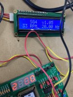
What a great build, thank you Pryamid! I aligned all three pots at 3.71VRMS and the reduced voltages at the numbers you gave. It hiccups a bit on startup, but runs smooth and switching between speeds is great. Maybe just needs a load on it.
And the motor fits in the cutout for the TD125 motor, so no major surgery there. Going to start working on the plinth and the layout for the controls.
Thanks again for all the help and apologies for asking questions there were already answered earlier in the thread.
Mike
Hi Pyramid,
I have a turntable with a subplatter of diameter 151.23 mm and a pulley of diameter 13.52 mm. T is 0.52 mm. According to your calculations, the frequencies must be 12.21 Kz and 16.49 Hz. Am I correct ?
What should be the nominal and reduced motor voltages for these values ?
Could you explain how you calculate these voltages ?
Many thanks !
Garrido-
Those numbers don't line up with any established motor or platter speeds. Those numbers would suggest a motor speed of ~370 RPM.
What are the specs for the existing motor (RPM, frequency & voltage)?
Which motor are you looking to replace it with (BLWS or BLWR series)?
Does your current pulley have the same center bore dimension as the BLWS shaft diam (0.25") or BLWR shaft (4mm)?
The nominal and reduce voltages are determined empirically and are different for BLWS or BLWR series.
Hi Pyramid,
Thank you for your quick response.
The current motor is a Papst GS 38.09 used on many older turntables. The supply voltage is 27 VDC or 24 VAC. The speed range is 400 ...600 rpm.
The current pulley has a 3 mm bore, the outside diameter of the pulley (in the centre) is 13.52 mm.
The motor I bought is the AA BLWS you recommend, with a bore of 0.25". I need a new pulley with the corresponding dimensions.
Got everything I need thanks to members here. Have a question: a 2A 15v PS is recommended for MA-3D/SG-4 combo. I'm building this for early Sota Cosmos, which uses LM317HVK to power the old Papst motor. LM is rated at 1.5A max, and supplies regulated 23V. I can replace the resistor on board to bring the voltage down, but will the current be enough? If it blows, expensive to replace ($70ea now). This would make a very graceful solution, I could use existing switches and everything... Thx
Attachments
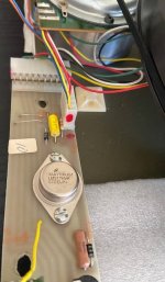
Thank you Mr. Pyramid!The LM317 should be OK at 1.5A. The SG4 draws minimum power and the MA3D is class D so it is 90-95% efficient.
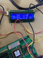
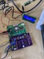
Happy to report that all electronics are working perfect! Now the mechanical part. I want to thank Pyramid and Ralph for their great help.
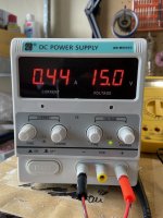
Max current draw I saw at 33 rom start-up at 840mA, which after about 2 sec drops to 440ma. Motor runs smooth. Minimal vibration in hand, should disappear in housing. Excellent project. I plan to house it in existing Sota body, only the LCD and switches will be located outside.
Max current draw I saw at 33 rom start-up at 840mA, which after about 2 sec drops to 440ma. Motor runs smooth. Minimal vibration in hand, should disappear in housing. Excellent project. I plan to house it in existing Sota body, only the LCD and switches will be located outside.
Attachments
Hi. This is proving to be too complicated. It will be easier to kill the original supply, and just use the original switch to manually turn-on the vacuum. I guess it’s possible to use some trigger from the SG-4 or MG, to add a relay etc but it becomes way above my expertise…The LM317 should be OK at 1.5A. The SG4 draws minimum power and the MA3D is class D so it is 90-95% efficient.

- Home
- Source & Line
- Analogue Source
- 3 Phase Class D amp for DIY BLDC motor Drive