BLDC fault
Hi Pyramid,
Well after a lot of checking i found that U2 was not outputting voltages due to the fact that that it was only getting 2.4 volts supplied (as opposed to 8v)
Found voltage reg U6 (78L08) was very hot and giving out 2.8 volts!!
Given that in retrospect one of the PC power supply i used may have been 19 volts, i dont know if i "frightened" it??
Off to lick my self inflected wound and look for a replacement, thanks pyramid, ill let ya know how i get on in setting up once replaced.
Must be near the bloody end soon!!
cheers
Johnny
Pully question origin live 10mm diamater
Hi boys,
I have been looking at origin live web site, they sell a nice pully but it's 10mm diameter, is that in the scope that the motor controller can accomadate?.., if so any idear what frequency that would be at 33 rpm with an 11.8 inch platter, my calculations don't make any sense to me !
My thanks as always.
Cheers Johnny ( currently struggling!)
My results so far
Thank You Pyramid for making this project available.
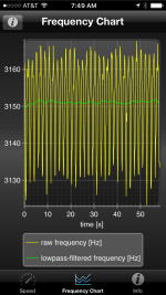
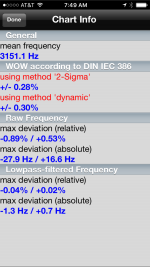
I've been playing around with the SG4 and now the Class D amp and motors from AA. I started with the BLWR as that was the only one in stock at the time. I am currently running 27.09/36.61hz using a stock size pulley. I have attached platterspeed graphs that show speed accuracy comparable with some high priced tables. My pulley is accurate to within .001 and think the absolute deviation is mostly due to the test record being quite off center.
I’m working on the BLWS now, (it is quieter as Pyramid stated). The pulley is also more accurate since I have a ¼” lathe mandrel to turn between centers. I should have it mounted later next week and will make graphs to compare.
Cheers,
Gregory
Thank You Pyramid for making this project available.
I've been playing around with the SG4 and now the Class D amp and motors from AA. I started with the BLWR as that was the only one in stock at the time. I am currently running 27.09/36.61hz using a stock size pulley. I have attached platterspeed graphs that show speed accuracy comparable with some high priced tables. My pulley is accurate to within .001 and think the absolute deviation is mostly due to the test record being quite off center.
I’m working on the BLWS now, (it is quieter as Pyramid stated). The pulley is also more accurate since I have a ¼” lathe mandrel to turn between centers. I should have it mounted later next week and will make graphs to compare.
Cheers,
Gregory
Attachments
Hi boys,
I have been looking at origin live web site, they sell a nice pully but it's 10mm diameter, is that in the scope that the motor controller can accomadate?.., if so any idear what frequency that would be at 33 rpm with an 11.8 inch platter, my calculations don't make any sense to me !
My thanks as always.
Cheers Johnny ( currently struggling!)
Motor RPM/Platter RPM= (Platter Dia + 1/2 T)/(Pulley Dia +1/2 T) Where T=Thickness of belt.
Assuming a 0.080" thick belt and rearranging terms:
Motor RPM=33.3*11.84/.4337
Motor=909 RPM w/10mm dia pulley @33.3 RPM
Motor RPM=60*Freq/pole pairs
The BLWS motor has 4 poles (2 pr) so rearranging terms:
Freq=909*2/60
Freq=30.3 Hz
You will have to increase the output voltage to 14VPP (4.95VRMS) at max output (SG4 set to 128) to compensate for the additional back EMF.
Last edited:
Thank You Pyramid for making this project available.
I've been playing around with the SG4 and now the Class D amp and motors from AA. I started with the BLWR as that was the only one in stock at the time. I am currently running 27.09/36.61hz using a stock size pulley. I have attached platterspeed graphs that show speed accuracy comparable with some high priced tables. My pulley is accurate to within .001 and think the absolute deviation is mostly due to the test record being quite off center.
I’m working on the BLWS now, (it is quieter as Pyramid stated). The pulley is also more accurate since I have a ¼” lathe mandrel to turn between centers. I should have it mounted later next week and will make graphs to compare.
Cheers,
Gregory
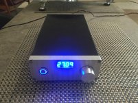
Great looking controller and great results! Which LED display did you use (Blue?)
If you are running the BLWS motor, the max output (SG4 at 128) should be 13.2VPP at 27 Hz and 15.6VPP at 36Hz. You can power the MA-3D with up to 24VDC without a problem (you'll need a higher supply than 15VDC to get 15.6VPP output).
Last edited:
Thank You, I used this New 0.36" 0.36 inch 7 Segment Display Blue LED 4 Digit Common Cathode | eBay and just used some scrap I had for the faceplate &Great looking controller and great results! Which LED display did you use (Blue?)
knob. The chassis was from a failed turntable controller I put together last year. No such issues with this one!
Thanks for the tip, I have some 24v supplies and will give it a go.If you are running the BLWS motor, the max output (SG4 at 128) should be 13.2VPP at 27 Hz and 15.6VPP at 36Hz. You can power the MA-3D with up to 24VDC without a problem (you'll need a higher supply than 15VDC to get 15.6VPP output).
Cheers,
Gregory
Sine wave gen tests
Hi pyramid and others, I bypassed U6 and put a lab PSU on to the 0v and 8 vpads of U6, (. Checked PSU with DVM that it was 8 v)
U2 somewhat warm, can keep finger on it for 12 seconds before uncomfortable.
With unit out of standby mode and set to 33rpm position and with respect to gnd on sine wave gen. And DVM set to A/C range I made the following measurments.
U5 pins 3/5/9 = 1.7 v a/c. U5 pins 4/6/8 = 1.7 volts A/C
Resistors 3/5/7 all. 1.75vA/C
U2 ( quite warm but not boiling) pins 5/10/12 = 0.95/1.03/1.03 respectively.
U2 inv I/p pin 6 = 0.58 V. Pins 9 /13 = 0.23 volt A/C
U2 o/p pins 7= 0.58 V A/C pins 8 and 14 both 0.23 volts A/c
O/ p seems to be dieing off in U2 and took out u6?.
Starting to get worried , if I have to remove U2 will I damage board doing so? I have solder sucking tool but this is a delicate board!....perhaps should have used IC sockets!?
Is it less damaging to get new PCB and start again? ( I have most of parts ordered as Spare except CPU and LED display and U8 and U6
At this point I am not sure.
An suggestions really welcome at this point.
Regards
Johnny
U2 should not get warm, it's probably damaged.
If you are not comfortable unsoldering it, use a small wire cutters or sharp X-Acto knife to cut off all of the leads to remove the body. Remove each of the pins with a tweezers and soldering iron, clean out the holes with solder-wick or solder sucker and replace U2.
If you are not comfortable unsoldering it, use a small wire cutters or sharp X-Acto knife to cut off all of the leads to remove the body. Remove each of the pins with a tweezers and soldering iron, clean out the holes with solder-wick or solder sucker and replace U2.
Status of me sine wave controller
Hi Mr pyramid ( and others)
Well, removed U6 and U2,put in a lm7809 in for U6, put a IC socket in for U2,
Got 8.7 volts on socket to U 2, put the IC in, could get 1.7 volts out on 0-90-120 but not for 240 ( no op from pin 8 /U2), all voltages to U5 to U2 identical for all phases, can set up MAD 3D as per instructions apart from 240 ( though voltages won't sum at Tp1 though 3phases set up identical to 4.2 volts?)
With respect to missing 240, I changed R5/R6 and C5/C6 I case I damaged any of them with heavy handed soldering?...still no 240.....changed U 2 still no 240,
Checked IC socket, have continuity from U5 pin 6 to r5 ( but that's not really the issues I have the same voltage at R5 as at the others, it just differs at r6, but that all been changed as I just stated above. I am stumped
So unfortunately 90 is a long way phase wise for 240, But is it possible to use the other wires or windings on a BLWR motor to get a phase relationship that will drive the motor with 0/90/120??..... Just in idear.
I am a newbie at this sort of thing, but just to be 100% certain the small red WiMa caps aren't fussy which way there inserted as far as I know ( unlike the tants and electrolytics which have polarity clearly marked)
Phew!!
Cheers Johnny
Check that you have 1.7VRMS on pins 5 & 6 of U5. If you don't have AC voltage on pin 5, check for 1.7VRMS on pin 7 of the uP; go directly to the lead on the chip, not the socket. If there is AC voltage there, CAREFULLY remove and reseat the uP. Ensure none of the pins on the uP or socket are bent.
Check all solder joints involved on U2 for breaks, shorts or broken traces.
Check all solder joints involved on U2 for breaks, shorts or broken traces.
Re-reading your last post, it appears that you have 1.7VRMS at U5 pin 6, so something is messed up with R5/R6/C5/C6.
If you can't sort it out, you could cut the trace between U5 pin 2 and R1 and add a jumper from U5 pin 6 to R1. The 240° waveform would then appear on the 90° output.
The Wima caps are not polarity sensitive.
The motor will not run from 0/90/120.
If you can't sort it out, you could cut the trace between U5 pin 2 and R1 and add a jumper from U5 pin 6 to R1. The 240° waveform would then appear on the 90° output.
The Wima caps are not polarity sensitive.
The motor will not run from 0/90/120.
hi Mr Pyramid
Hi Sir, thank you for your patience,
Did all you suggested prior to post, no joy,
(i have physical continuinity between the leg 5 to R 22 and the leg of pin 6 to RC3)...I am now baffaled by paralysis- through analysis (time for a diffrent approach)
but when i as in bed i thought as i think you are suggesting in the last post (i heard the last post playing in my head when i was about to give up last night.)
why not use the 240 out put of U5 pin 6 (1.7 v RMS the voltage same as the 0/120 so its generated)- then via a wire link to R 1 on the 90 side (useing r1/r2/c1/c2/and U2 a pins 3 and 2 to get an output from pin 1 (which i know works as i allready get the correct reading from the 90 side as things stand now.
just rember that 90 on the Sine wave Gen is actully now 240 and carry n as "normal" from there.
However i would now have to stop the 90Hz from U 5a pin 2 but cutting the trace as you suggested.
this is the way to go as i now have no othere option
Thanks to you boss
very best regards
Johnny
Hi Sir, thank you for your patience,
Did all you suggested prior to post, no joy,
(i have physical continuinity between the leg 5 to R 22 and the leg of pin 6 to RC3)...I am now baffaled by paralysis- through analysis (time for a diffrent approach)
but when i as in bed i thought as i think you are suggesting in the last post (i heard the last post playing in my head when i was about to give up last night
.)why not use the 240 out put of U5 pin 6 (1.7 v RMS the voltage same as the 0/120 so its generated)- then via a wire link to R 1 on the 90 side (useing r1/r2/c1/c2/and U2 a pins 3 and 2 to get an output from pin 1 (which i know works as i allready get the correct reading from the 90 side as things stand now.
just rember that 90 on the Sine wave Gen is actully now 240 and carry n as "normal" from there.
However i would now have to stop the 90Hz from U 5a pin 2 but cutting the trace as you suggested.
this is the way to go as i now have no othere option
Thanks to you boss
very best regards
Johnny
Last edited:
Fixed it eventully
Hi Pyramid (and others)
Insterd of cutting tracks i lifeted the required resistors and jumpered the 240 degrees to the 90 degrees, that set up the Ma3D, got all the 3 required voltages set up, looking good.. connected the motor and the MA3D made a ticking sound and no motor rotation?...ticking was comeing from an electrolytic, figured it must be shorting internally?, changed that, no ticking but no rotation, the motor pod i made had slipped around and sheared all 3 motor wires off, secured the pod with a bolt to stop rotatation and soldered and insulated the wires now have rotation, at last!
(6 hour stint)
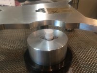
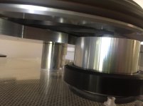
My thanks to pyramid for all his assistence and patience, now have to find out why the shaft reducer i got (4 mm to 3/16) just spins on the shaft? (unless a HRX pully clamps it up againsed the motor shaft when you stick it in the pully
and plop it on the shaft?
Steep learning curve for a newbee but well worth it (i think?)
Best to all..a very helpfull forum, lots of good will
Johnny
Hi Pyramid (and others)
Insterd of cutting tracks i lifeted the required resistors and jumpered the 240 degrees to the 90 degrees, that set up the Ma3D, got all the 3 required voltages set up, looking good.. connected the motor and the MA3D made a ticking sound and no motor rotation?...ticking was comeing from an electrolytic, figured it must be shorting internally?, changed that, no ticking but no rotation, the motor pod i made had slipped around and sheared all 3 motor wires off, secured the pod with a bolt to stop rotatation and soldered and insulated the wires now have rotation, at last!
(6 hour stint)
My thanks to pyramid for all his assistence and patience, now have to find out why the shaft reducer i got (4 mm to 3/16) just spins on the shaft? (unless a HRX pully clamps it up againsed the motor shaft when you stick it in the pully
and plop it on the shaft?
Steep learning curve for a newbee but well worth it (i think?)
Best to all..a very helpfull forum, lots of good will
Johnny
- Home
- Source & Line
- Analogue Source
- 3 Phase Class D amp for DIY BLDC motor Drive