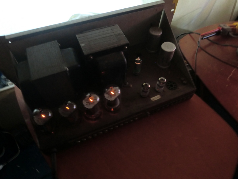
That was often the case for EI cored, multiple interleaved hi-fi transformers with good low frequency response - especially for early Williamson rated OT's.That is the output transformer and it is actually larger than the power transformer by about 1/2" in size.
You hit the nail on the head on your post #s 18 & 23. These were either special ordered amps or a previous owner changed out the output transformers in these. The "smallest" transformer that you referred to earlier is the power supply choke shown in Jazbo8's schematic in post #2. The original output transformer in these were great quality OTs and can do 20Hz at nice power levels. The originals had 1750 ohm plate to plate primary impedance and 6 secondaries at 1.4 ohms each. These were meant for PA applications where they would be configured as 25 volt or 70 volt line transformers and not hooked up directly to loudspeakers... But that doesn't mean that they can't be hooked directly to speakers; they can. The two most common ways to hook the secondaries up for common loudspeaker impedances is either in parallel-series (5.6 ohms) or series-parallel (12.6 ohms). These two choices will cover 4, 8, or 16 ohm speakers.
Since the output tubes are sweep tubes, they like working into a lowish primary OT impedance since they are capable of delivering LOTS of current compared to the common audio tubes. What I would do with your amps is find out what output transformers they have installed in them, as they aren't the normal original ones. If you have a low voltage transformer (filament) you can inject AC voltage into the primary winding and take voltage measurements for each secondary to determine what the impedances are of the transformer. I have 4 of these that I got in a trade and was skeptical at first as to their quality but when rebuilt as in the schematic above, they make worthy Hi-Fi amps; they sound really good!
Good luck!
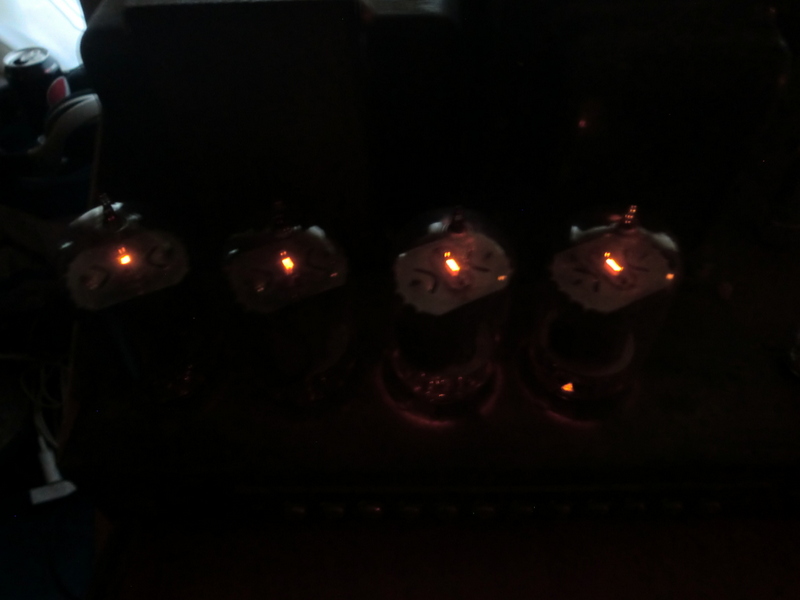
Oh! One more thing... I installed a second bias adjustment pot in my amps as it's going to be next to impossible to find 4 matching output tubes for each amp. By installing a second bias pot in each amp, matched pairs can be used instead.
By the way... I think I have an extra "Precision Electronics" nameplate for your 3rd amp. You have the important stuff, so you could easily get all 3 working again.
By the way... I think I have an extra "Precision Electronics" nameplate for your 3rd amp. You have the important stuff, so you could easily get all 3 working again.
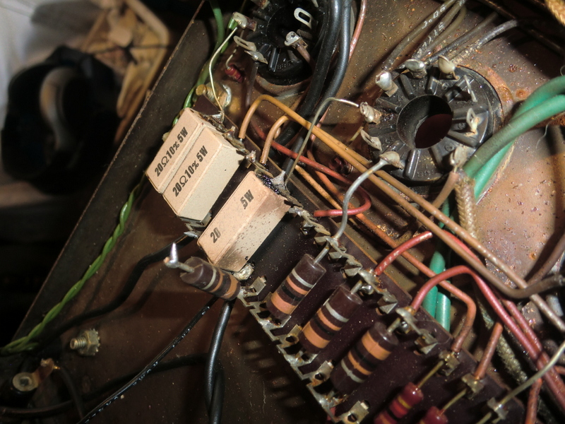
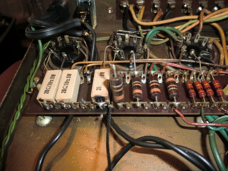
Yes I was thinking about the addition of extra pots for the bias adjustment. Did you consider using 4? Then you could adjust each tube. I have a bunch of extra NOS pots that might just work? I do have the other face plate but it is broken. Also one amp is really going to take a lot to get going. It has visible heat damage. It got so hot one of the resisters unsoldered it's self. You can also see that the ceramic one next to that resistor got real hot also. So I am looking at it right now as a parts unit. But I will keep in mind your face plate.
Thanks
Thanks
An externally hosted image should be here but it was not working when we last tested it.
An externally hosted image should be here but it was not working when we last tested it.
An externally hosted image should be here but it was not working when we last tested it.
 - - the output transformer's end bells and insulating washers on their bolts look the same as those on the power transformers.
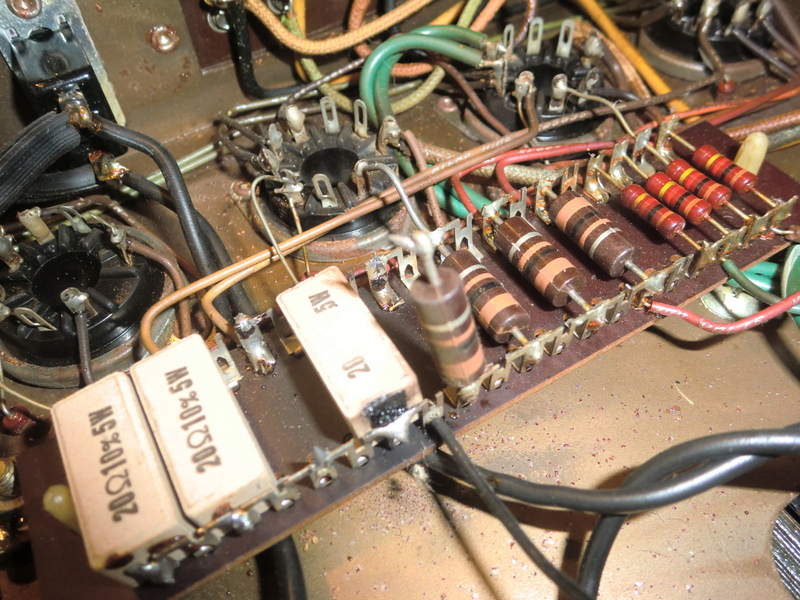
I wouldn't worry about the overloaded 20 ohm cathode resistors, they were just taking the fall for a bad valve. As long as the output transformer primary windings and power transformer HT windings are still ok then that is the key. The carbonisation just needs a clean up - there is no apparent high voltage in that area for tracking to be an issue except across to the screen stopper terminals. If the related 100ohm screen stopper didn't burn out then that would normally indicate a bad grid coupling cap, but one cap serves two tubes.
Some would be inclined to now use 20 ohm 2W resistors, to act as a better poor mans fuse, especially if you add a parallel 47k resistor to maintain cathode voltage if a fault occurs. The 5W variety just prolong the stress for other parts of the amp.
Some would be inclined to now use 20 ohm 2W resistors, to act as a better poor mans fuse, especially if you add a parallel 47k resistor to maintain cathode voltage if a fault occurs. The 5W variety just prolong the stress for other parts of the amp.
Last edited:
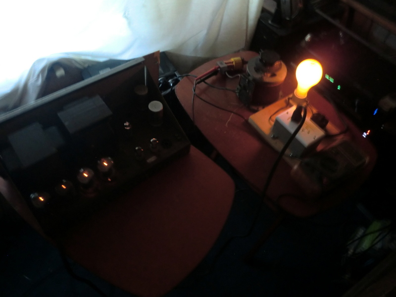
Well I fired one up after examining it. It looked like someone had replaced the capacitors on it so I got out my variac and my dim bulb tester and slowly powered it up over about 1 hour. It looked good with no bad smells or bad sounds. I checked for DC offset and it was about .01mv! So I got a cheap speaker that I don't care about (Bose 401) and hooked it up with my CD player as the input. I was very impressed! On lowest volume there was no strange hums or other offensive noises. I mean it is dead quiet until you turn up the volume and then WOW. This amp is very powerful and only sound better the higher the volume goes. Just for clarity I am in no way going to just leave this amp like it is. I am still going to completely pull it apart and replace all the capacitors and anything else it needs. But it was real fun to here it
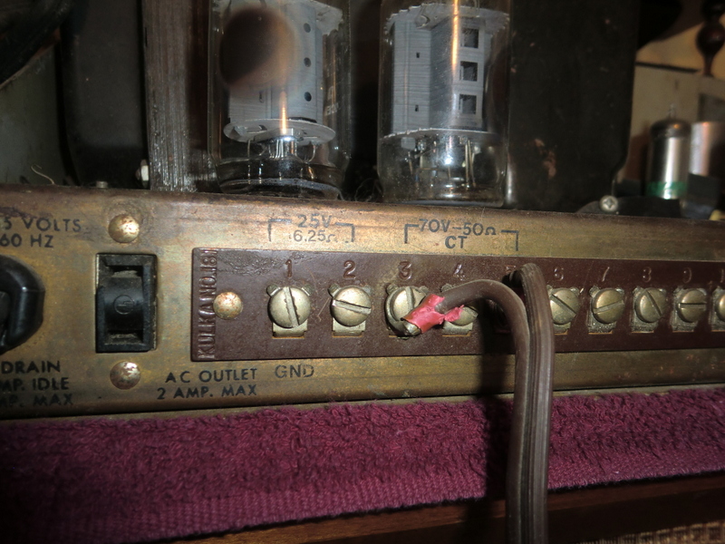
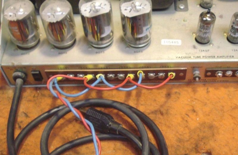
Okay yesterday I hooked one up and got it playing. Now I used the jumper pattern I found at first but when I did I got zero output. So I just hooked up my speaker to the 25v 6.25ohm section on the back of my amp and it played great. Well today I took a better look at the pics of the others on the net and here is another difference on mine you don't see on others. On the back of the others you see the jumper symbols above the output terminals. On the back of mine it just tells you to hook it to pins 1 and 2 for 6.25ohms and pins 3 and 5 for 50ohm out. I have come to the conclusion that my amps are definitely wired different than the other G 101 A amps. Here is a pic of the back of mine and one from the others on the net. You can see the different markings on the outputs. The one with the blue and red wires is off the net.
Last edited:
... I checked for DC offset and it was about .01mv! ...
New to tube amps?
A transformer output can NOT have "DC offset". (Unless there is a horrid breakdown inside the transformer; even then usually not.)
For future: Bring it up on a big 10 Ohm resistor. Look for big _AC_ Volts (oscillations or big buzz). If "OK", tap your test-speaker quickly, just in case it is screaming enough to wake the neighbors. If that goes quietly, wire the test speaker and an input.
- Status
- This old topic is closed. If you want to reopen this topic, contact a moderator using the "Report Post" button.
- Home
- Amplifiers
- Tubes / Valves
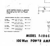
- 3 Grommes Precision G101A, 100 watt mono block tube amps