i have a mono 100w version of that board zek. it has a noise floor. could be even worser but it could also be a lot better. its not hifi. more like cheap crap meh-fi. sure boards are a lot lot better.
Sure Electronics' webstore Search results for: 'tpa3116 100w'
Sure Electronics' webstore Search results for: 'tpa3116 100w'
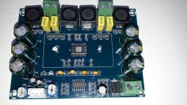
It's a fake, it has only one chip.
Attachments
I've narrowed down to Rubycon ZLH and Panasonic FR, 1.488A/17 mOhm and 1.95A/18 mOhm respectively
10k hours rating, bit of overkill but I know I'll never need to replace them ever.
Are they suitable for that application? The panny is 22cents more expensive but with a higher ripple current rating.
Thanks!
I use Rubycon ZLHs exclusively on my Class D amps (sometimes FC if I'm out of ZLH) in values close to the datasheet (in other words, not in large values like 1000uF or 2200uF, but 330uF or 470uF). For the input caps, MKT1822 2.2uF and I find the combination is pleasing to me, though the sound can be described as "sharp," as opposed to "warm" with some sibilance at times. I like the detail that results, very resolving, which to me is the whole reason to go with Class D amps in the first place.
Does anyone have some experience with this board?
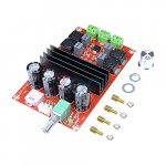
2x100W TPA3116 D2 Dual Channel Digital Audio Amplifier Board 12V-24V for Arduino | eBay
2x100W TPA3116 D2 Dual Channel Digital Audio Amplifier Board 12V-24V for Arduino | eBay
Does anyone have some experience with this board?
2x100W TPA3116 D2 Dual Channel Digital Audio Amplifier Board 12V-24V for Arduino | eBay
Yep, lots do. Poultygeist was the first I read of using it, I think. Mine is connected to a Chromecast audio but not currently in use. It sounds good. It won't do 2x100 watts into 8 ohms. It needs a 4 ohm load to approach that. I have read that it isn't really suited for high output use. The solder tracks are thought to be "puny" by some. Used at 16-19V and with normal indoor listening levels it's fine.
.... It won't do 2x100 watts into 8 ohms. It needs a 2 (not 4) ohm load to approach that. I have read that it isn't really suited for high output use. The solder tracks are thought to be "puny" by some. Used at 16-19V and with normal indoor listening levels it's fine.
Put some 105dB/W(very sensitive) 2ohm speakers on them and come back to tell us, it wasn't loud.
")
You will get about 100W from pbtl tpa3116 at 2ohm, 50w@4ohm, 25W@8ohm with 26V. With 18V you get about half.
The 2 chip 2x100w boards are only louder then the 1 chip boards, when you put a 2ohm load/speakers on them.
Last edited:
Member
Joined 2018
JSXINGHE XH-M543 Modification
Hi Guys
I had traced XH-M543 V9 (Single Chip BTL 2ch) board.
I 'm going to modify following pints.
Hi Guys
I had traced XH-M543 V9 (Single Chip BTL 2ch) board.
I 'm going to modify following pints.
- Reduce the gain (Input sens. 20mV --> 1V)
- Switching frequency change (400kHz --> 1.2MHz)
- Muting Driver Circuit Modification (1Cap to Active Circuit)
- MLCC to anther type (Audio Signal Coupling Caps)
- Paste Silicone Grease on thermal PAD
Attachments
If I compare the schematic with the PCB I miss the C34 330uF used for muting during power up. I had the previous version with only a resister from mute to ground and that was giving a loud plop during power off. I wonder if this has been improved with this version.
Was the heatsink removable by removing only screws?
Was the heatsink removable by removing only screws?
Member
Joined 2018
Member
Joined 2018
HX-M543 Modification
I'm modifying Single TPA3116D2 Board XH-M543.
Modification details will be described in following page...
TPA3116D2 2 channel Amprefire Modification
Current modification plan as follows...
I'm modifying Single TPA3116D2 Board XH-M543.
Modification details will be described in following page...
TPA3116D2 2 channel Amprefire Modification
Current modification plan as follows...
Attachments
Last edited:
Member
Joined 2018
Was it original in slave mode? (Gain: 47k and 47K)
Oh~!, Thank you for your advice.
It was just Copy, Paste and My mistake ....
Updated!
Attachments
Last edited:
If I compare the schematic with the PCB I miss the C34 330uF used for muting during power up. I had the previous version with only a resister from mute to ground and that was giving a loud plop during power off. I wonder if this has been improved with this version.
Was the heatsink removable by removing only screws?
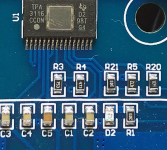
I have found C34! Its one of the 3 capacitors near the connector for the power.
If I look to the PCB, it looks as if R21 was not between R5 and C34, but between R5 and the Mute pin (pin 12 of the TPA3118) It looks as if R21 is used to limit the current to the mute pin.
And are you sure R1 (near the power LED) and R20 is connected to VCC? Because on the PCB it goes down with a via, just before the big VCC track. Wasn't it connected to C34?
Member
Joined 2018
I have found C34! Its one of the 3 capacitors near the connector for the power.
If I look to the PCB, it looks as if R21 was not between R5 and C34, but between R5 and the Mute pin (pin 12 of the TPA3118) It looks as if R21 is used to limit the current to the mute pin.
And are you sure R1 (near the power LED) and R20 is connected to VCC? Because on the PCB it goes down with a via, just before the big VCC track. Wasn't it connected to C34?
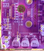
I made a X-Ray Like View. It shows R21 is connected in series to the MUTE pin. R20 and R1 are tied to VCC..(May be I need some fix on my schematic ...)
Attachments
Member
Joined 2018
Can someone tell me what kind of connection the input is (white 3-pin connector). I have the same on another but don't know what it is.
I guess it's a JST's "XH" type connector or it's compatible.
I have bought a m190 amplifier module with two chips. It works flawlessly however it suffers from pop at turning off. No hiss, no noise nothing al all. I am using a 12V 5A switching power supply. The only problem that is bothering is, as I mentioned, a very subtle pop exactly when I turn the amplifier off. I have spent a lot of time reading your posts but could not find a solution. Could you please help me find a solution? Thanks in advance. Image is taken from Amazon but it is exactly the module that I have.
Attachments
I googled and found this, basically a simple circuit that mutes the amp
Final Solution for anti-pop on Sure TPA3116
TPA3132D2 - on-delay and emergency shut-down (anti-pop) - also for TPA3116 / TPA3118 - #360customs
Final Solution for anti-pop on Sure TPA3116
TPA3132D2 - on-delay and emergency shut-down (anti-pop) - also for TPA3116 / TPA3118 - #360customs
- Status
- This old topic is closed. If you want to reopen this topic, contact a moderator using the "Report Post" button.
- Home
- Amplifiers
- Class D
- 2x100W TPA3116D2 (2 chips, each in PBTL)