@ Stratus.
which display do you have in mind? The hantek PC Scopes or the Elektor spec analyzer??
I deleted the original post (#1) in my first reply as it is very long and I didn't know how to snip out the irrelevant parts.
I was looking at the video waveforms from post #1 and found them to be useless for repairing or calibrating any video gear whether professional or home use.
G²
Some of the ATMega packages make nice AWGs. ;-) My two bits is that if its bandwidth and sampling rate with low price that are priorities, then Hantek, Elektor and the Pluto boards take the cake. Multimeters and waveform generators are stuff one can buy or homebrew under $50 or better still get them out of free open source softwares out there that use soundcards if its under 20Khz we're talking of.
Last edited:
Thanks for G2's comments. We have tested the signal again as we are confident very much about our DSOs. The following factors would potentially affect the test results:
1. The quality of the test signals burned in the test VCD
We used a freely downloaded program to burn the test CD. As the program could only generate NTSC video file, so we used another program to convert it to PAL before burning it to the CD. We only had a PAL VCD player.
We used the same VCD last time and this time.
2. The quality of the VCD player.
Last time, we used a VCD player from Wearnes (do not know where it is now )
)
This time, we used a VCD player from Pioneer .
Both were cheap ones, though.
3. The connection cable between the DSO probe and the video output of the VCD player.
Last time, we ran a quite long cable (about 2 m for connection convenience) between the output jack of the VCD player and the probe of the DSO. There was a video splitter in between so that we could measure the signal on the DSO and at the same time monitor the video test pattern on a TV screen.
This time, we shortened the cable to a length of only about 5cm.
4. The proble switch position
The probe we used had a bandwidth from DC~6MHz at x1, and DC~60MHz at x 10.
Last time, we used x1.
This time, we used x10.
5. The quality of the probe
6. The quality of the our DSOs
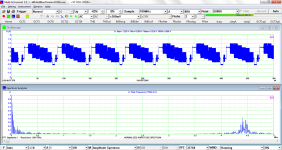
Attached is the screenshot obtained this time. It was measured using VT DSO-2810H.
By comparing the results, we can conclude that the attenuation of the high frequency components in those screent shots last time could be mostly attributed to the long cable used between the VCD player and the DSO in the previous tests. The probe switch position x10 can improve the magnitude measurement accuracy at high frequencies.
1. The quality of the test signals burned in the test VCD
We used a freely downloaded program to burn the test CD. As the program could only generate NTSC video file, so we used another program to convert it to PAL before burning it to the CD. We only had a PAL VCD player.
We used the same VCD last time and this time.
2. The quality of the VCD player.
Last time, we used a VCD player from Wearnes (do not know where it is now
)This time, we used a VCD player from Pioneer .
Both were cheap ones, though.
3. The connection cable between the DSO probe and the video output of the VCD player.
Last time, we ran a quite long cable (about 2 m for connection convenience) between the output jack of the VCD player and the probe of the DSO. There was a video splitter in between so that we could measure the signal on the DSO and at the same time monitor the video test pattern on a TV screen.
This time, we shortened the cable to a length of only about 5cm.
4. The proble switch position
The probe we used had a bandwidth from DC~6MHz at x1, and DC~60MHz at x 10.
Last time, we used x1.
This time, we used x10.
5. The quality of the probe
6. The quality of the our DSOs
Attached is the screenshot obtained this time. It was measured using VT DSO-2810H.
By comparing the results, we can conclude that the attenuation of the high frequency components in those screent shots last time could be mostly attributed to the long cable used between the VCD player and the DSO in the previous tests. The probe switch position x10 can improve the magnitude measurement accuracy at high frequencies.
Attachments
Virtinis
USB 3 apears to be quite a big improvment
When would you espect to market USB 3 instruments?
It depends on when our favourite USB interfacing chip supplier can give us an acceptable price.
. By the way, as mentioned by Regal, thunderbolt and USB3.0 are still fighting there.....