Pretty cool what you are presenting here! Would be really nice to post some explanation and some asc files ...Trying to fit the model across such a large range of operating current seems to expose the limitations of even the newest model parameters. I can fit one curve but I can't fit them all...
")
BR, Toni
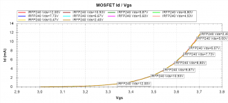
Vgs vs Id curves for MOSFETs and FETs would also be useful. Your DCA should be able to show us the right subthreshold curve for most MOSFETs.
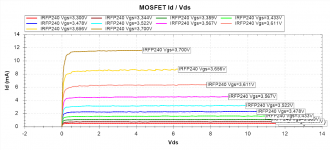
Something like this? Which of these 2 graphs do you need? Which settings?
BR, Toni
Attachments
... some more bjt data ...
TO-2SK170GR Id Vds
TO-2SK170GR Id Vgs
FC-BD139-16 hFe=160 dc=A34
FC-BD140-16 hFe=180 dc=A02
FC-KSA1220AY hFe=250 dc=B33
FC-KSC2690AY hFe=270 dc=B43
SX-IRFP240 Id Vds
SX-IRFP240 Id Vgs
SX-IRFP9240 Id Vds
SX-IRFP9240 Id Vgs
FC-KSA1381E hFe=143 dc=C12
FC-KSC3503D hFe=75 dc=C21
TO-2SA1507T-4E hFe=300 dc=1422
TO-2SA1837 hFe=145 dc=1306
TO-2SC3902T-3A hFe=250 dc=1305
TO-2SC4793 hFe=200 dc=1305
US-2SA1837LB hFe=210 dc=Z0092
US-2SC4793LB hFe=200 dc=Z0026
Vendor:
FC - Fairchild Semi
SX - Siliconix/Vishay
TO - Toshiba
US - Unisonic
Attachments
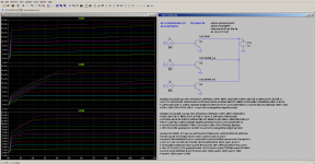
Since the standard quasi-saturation model is buggy right now, I'm experimenting with VBIC which should be an improvement if I can figure out how it works. Here is an experimental VBIC model:
.model KSC1845F_FC npn level=9 ibei=3.07266e-016 vef=180 ikf=0.35 nkf=0.66
+ iben=1e-015 is=1.075431e-013 nei=1 nen=2 ncn=1.5 nci=1
+ ibci=5.97461666666667e-014 ver=20.6691 ikr=0.0190546 ibcn=1e-015 ibcip=0.01
+ re=1.5 rcx=0 rci=165 rbx=12.092 rbi=144.908 kfn=0 afn=0 cje=1.8e-011
+ cjc=2.0482313496121e-023 cjcp=0 tf=4.2e-010 xtf=1 itf=0.02 td=0 fc=0.5 xis=3
+ xii=1.2719 xin=1.2719 gamm=9e-006 vo=3.8 hrcf=1 pe=0.7300286 me=0.3619943
+ pc=0.5 mc=0.3659045 ps=0.75 ms=0 ea=1.1809 eaie=1.1809 eaic=1.1809
+ eane=1.1809 eanc=1.1809
Maybe it's time for a thread split?
...
Maybe it's time for a thread split?
Feel free to do so. Of course you can also add your results in this thread as we like to use your spice models for power amplifier design!
BR, Toni
My first model was based on the Fairchild datasheet, which was just a badly redigitized NEC datasheet. So it does represent a device that was commonly available at one time. I am keeping that model, but as 2SC1845 and changing the MFG field to NEC. This is why it's a bad idea to leave out MFG and date code when making models.
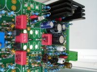
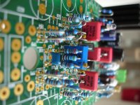
sa2015
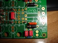
Some early steps
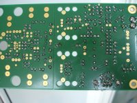
Solder side,still unwashed
Some early steps
Solder side,still unwashed
Attachments
SA2015
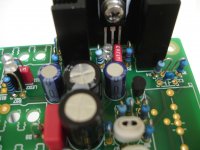
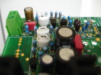
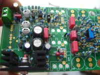
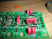
Dear Toni, is it nessecery a MKP10 (47nf)here?In this case i must drill the pcb to fit, or a MKT that fit well?
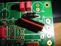
Is this coil ok,i can't see an advaice for wire diameter.This was made using 1mm coil(19 turns 8mm D=8mm) wire and measure 0.8μH.
Don't look at the(coil) position,still unsoldered.
Any advandage using KSC3503E in position of Q13?
Dear Toni, is it nessecery a MKP10 (47nf)here?In this case i must drill the pcb to fit, or a MKT that fit well?
Is this coil ok,i can't see an advaice for wire diameter.This was made using 1mm coil(19 turns 8mm D=8mm) wire and measure 0.8μH.
Don't look at the(coil) position,still unsoldered.
Any advandage using KSC3503E in position of Q13?
Attachments
Last edited:
Is the capacitor acting as a filter of the audio frequencies, or is it a coupling capacitor where the filtering frequency is many octaves away from the audio frequency range?
If filtering audio then use polypropylene.
If coupling then use MKT/MKS/Electrolytic.
I would use a much larger mandrill diameter and wind on fewer turns to give a diameter = coil length.
8Turns around an AA battery gives ~0.7 to 0.8uH
And I prefer much thicker wire. Anywhere from 1.4mm diam to 3.1mm diam for a 100W amp.
Dear Toni, is it nessecery a MKP10 (47nf)here?In this case i must drill the pcb to fit, or a MKT that fit well?
Is this coil ok,i can't see an advaice for wire diameter.This was made using 1mm coil(19 turns 8mm D=8mm) wire and measure 0.8μH.
Don't look at the(coil) position,still unsoldered.
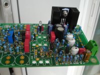
Dear Thimios,
looks great so far!

Use a MKP4, 47nF, 400Vdc or any other MKP which fits (have I forgotten to send you such beats?). MKT as zobel may be used here too. Don't think here will be big measurement differences if you use them as second source.
Diameter of your coil is OK - I have used a 7mm HSS drill to generate the coil - gives 8mm diameter when using 1mm wire. It will fit exactly into the holes if you start producing the coil using the correct direction ...
Have fun,

Toni
The Output Zobel gives a load for the high frequencies to help keep the amplifier stable.
ONLY high frequencies pass through the R+C and providing you allow the HF current to pas then you don't hear those high frequencies.
You can use MKT/MKS/MKP or any plastic film capacitor.
If you have a very high power amplifier where considerable HF current could pass, then the esr must be low enough to not overheat the capacitor.
I use 150V MKT for 100W amplifiers.
The Output Zobel gives a load for the high frequencies to help keep the amplifier stable.
ONLY high frequencies pass through the R+C and providing you allow the HF current to pas then you don't hear those high frequencies.
You can use MKT/MKS/MKP or any plastic film capacitor.
If you have a very high power amplifier where considerable HF current could pass, then the esr must be low enough to not overheat the capacitor.
I use 150V MKT for 100W amplifiers.
If this cap at this position gets hot then there will be a major problem with this amplifier ...
I have seen many Mambers testing their amplifiers with 20kHz and higher squarewaves. Some even use 100kHz and 200kHz squarewaves.
The HF content of a squarewave heats up the esr of the Output Zobel.
The HF content of a squarewave heats up the esr of the Output Zobel.
Yes, the operator !If this cap at this position gets hot then there will be a major problem with this amplifier
It's no problem to use here higher hFe KSC3503. I have designed the amp to be able to use the still available KSC3503-D. Higher hFe at this position should be of no problem....
Any advandage using KSC3503E in position of Q13?
have I forgotten to send you such beats?Dear Thimios,
looks great so far!
Use a MKP4, 47nF, 400Vdc or any other MKP which fits (have I forgotten to send you such beats?). MKT as zobel may be used here too. Don't think here will be big measurement differences if you use them as second source.
Diameter of your coil is OK - I have used a 7mm HSS drill to generate the coil - gives 8mm diameter when using 1mm wire. It will fit exactly into the holes if you start producing the coil using the correct direction ...
Have fun,
Toni
No,you sent me this MKP10 but this don't fit well
Now i can tell that all parts for this amplifier is a donation from Toni.
Toni thank you very much.
- Home
- Amplifiers
- Solid State
- 2stageEF high performance class AB power amp / 200W8R / 400W4R