Tons of 22000uf/80v!Of course you are right. For me it is a (very little) disaster because I have tons of 22000µF/80V with 5 pin layout ...

Of course you are right. For me it is a (very little) disaster because I have tons of 22000µF/80V with 5 pin layout ...
Ah, now it's getting clearer! I've been wondering why you've provided this 5 pin footprint at all, 'cause these parts are the most expensiest of all, at least here in Germany
 .
.Another question: Did you do any layouts with a single diode bridge for both rails? As stated yet, I don't see any advantages in two bridges.
Best regards!
Ah, now it's getting clearer! I've been wondering why you've provided this 5 pin footprint at all, 'cause these parts are the most expensiest of all, at least here in Germany
Another question: Did you do any layouts with a single diode bridge for both rails? As stated yet, I don't see any advantages in two bridges.
Best regards!
All my previous power supply designs are single diode bridge - nothing wrong doing so. Just wanted to bring it to the max.
According to recommendations of e.g. Bob Cordell and Nelson Pass I decided to develop a dual diode bridge power supply just 4 fun.
Have Fun, Toni
34 pieces ...Tons of 22000uf/80v!
of this premium parts : EKMH800VQT223MB80T United Chemi-Con | Kondensatoren | DigiKey
The upcoming amplifier project needs many of this parts (mono block 3 channel 3 way analog crossover - optional 3 way digital crossover) ...
Fun!
BR, Toni
Last edited:
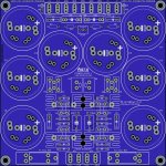
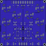
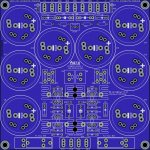
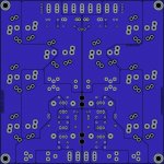
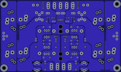
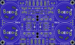
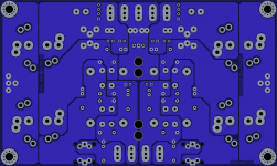
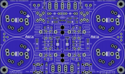
SA2014/SA2015/SA2016 power supply ...
Attached the corrected version. Now the 5pin lytic layout should be OK. Have a look on it and please report any errors ...
Attached the corrected version. Now the 5pin lytic layout should be OK. Have a look on it and please report any errors ...
Attachments
-
 sa2014_power_supply_2pin_diodes_big_pcb_top.jpg892.4 KB · Views: 913
 -
 sa2014_power_supply_2pin_diodes_big_pcb_bottom.jpg462.2 KB · Views: 866
 -
 sa2014_power_supply_3pin_diodes_big_pcb_top.jpg893.3 KB · Views: 836
 -
 sa2014_power_supply_3pin_diodes_big_pcb_bottom.jpg464.9 KB · Views: 793
 -
 sa2014_power_supply_3pin_diodes_small_pcb_bottom.png613.4 KB · Views: 190
 -
 sa2014_power_supply_3pin_diodes_small_pcb_top.png682.6 KB · Views: 190
 -
 sa2014_power_supply_2pin_diodes_small_pcb_bottom.png613.1 KB · Views: 203
 -
 sa2014_power_supply_2pin_diodes_small_pcb_top.png681.3 KB · Views: 709
SA2014/SA2015/SA2016 power supply ...
Note: Gerbers are free to use only for non commercial DIY projects.
Changes from v4.1 to 4.2:
BR, Toni
Note: Gerbers are free to use only for non commercial DIY projects.
Changes from v4.1 to 4.2:
- 5pin lytic footprint should be now OK
BR, Toni
Attachments
-
sa2014_power_supply_3pin_diodes_small_pcb.zip261.9 KB · Views: 246
-
sa2014_power_supply_2pin_diodes_small_pcb.zip279.9 KB · Views: 229
-
sa2014_power_supply_3pin_diodes_big_pcb.zip350.3 KB · Views: 229
-
sa2014_power_supply_2pin_diodes_big_pcb.zip369.2 KB · Views: 241
-
sa2014_power_supply_3pin_diodes_small_pcb.pdf685.6 KB · Views: 294
-
sa2014_power_supply_2pin_diodes_small_pcb.pdf712.5 KB · Views: 274
-
sa2014_power_supply_3pin_diodes_big_pcb.pdf876.9 KB · Views: 295
-
sa2014_power_supply_2pin_diodes_big_pcb.pdf901.6 KB · Views: 360
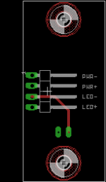
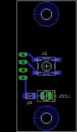
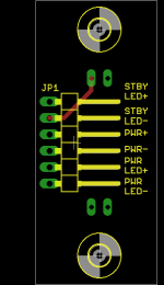
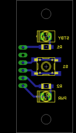
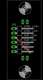
A very, very simple front panel switch PCB for diyAudio projects. Toni's Main Control Unit can be set up for a momentary action switch for power-on. This PCB has a little 6x6mm momentary, normally-open, tactile switch and LED for power on/indication. (It could easily be revised to add a standby LED also which Toni's MCU provides for.) The actuator is up to the user. Perhaps a 'button' from aluminium rod, brushed to match the front panel with a simple o-ring to hold it in place a la my builds.
Board is 20mm x 44mm and the LED is 10mm down from centre of switch. I'm going to do a panel run of these and so will have a lot of spares if anyone is interested.
Board is 20mm x 44mm and the LED is 10mm down from centre of switch. I'm going to do a panel run of these and so will have a lot of spares if anyone is interested.
Attachments
SA2014/SA2015/SA2016 power supply ...
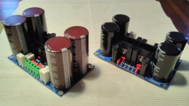
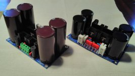
... working samples!
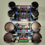
First picture:
... working samples!
First picture:
- High voltage, high power version for SA2014 see pcb on left side (max. +/-80V)
- Lower voltage version for SA2015 and SA2016 see pcb right side (max +/-50V)
Attachments
Last edited:
Dear Steve,
nice idea! Could you add a standby led position too to be universal?
BTW: I like your cool looking front design!
BR, Toni
Thanks!
Yes, I can add. I am 'stuck' with my power-on indication LED 1cm below the centre of the power button to maintain consistency with previous builds. I could add the power standby LED 1cm above it. Symmetrical.

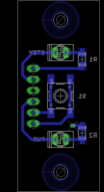
Yes, R5 and R6!Nice. What's the tall, white, rectangular OMC resistor? (R5, R6) Those vertical fuses look the bees knees.
Regarding vertical fuses: was a really good idea of you! I never have seen the vertical fuses before you brought them to my attention...
Sorry: Ohmite TWM5J series.I meant what part is it? I've not seen a resistor like that before.
See attached revised panel switch board.
Would it be possible for you to rearrange the connector of the led's to be pin compatible with the housekeeping pcb?
Thx!
BR, Toni
Ok I think this matches. Perhaps you can double check. (It is a bit confusing because the pin orientation of the symbol in Eagle is different from the package orientation.) This should also allow a 4-pin Molex or similar as with the MCU board and a 2-pin directly under it - connectors mounted with 'clip' to the left, pins to the right. I wanted to make sure it works okay with a right-angled 6-pin header (0.254 pitch) for those situations where space is at a premium.
Attachments
- Home
- Amplifiers
- Solid State
- 2stageEF high performance class AB power amp / 200W8R / 400W4R