With degenerating resistor we have degenerated transconductanse:gm'=gm/1+gm*Re.Linearised, but gain goes down.I have been using 200mV to 300mV as the Vdrop of the degeneration resistor, in LTP, & VAS & Current Mirror.
What is wrong with doing it that way? excess added noise? or many other avoidable problems?
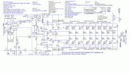
Final Cherry version
Then followed a long period of trial & error, trying to remember what worked in Jurassic ‘real life’ times; finally resulting in Cherry.gif Each step was checked for stability as in #177
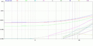
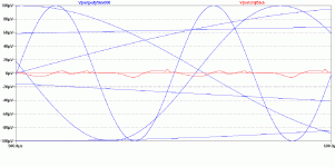
CherryTHD.gif & Cherry20k.gif show what was finally achieved.
Several changes to component values made small improvements but the major gains were by using a smaller Cherry cap C1 47p and doubling Gm for the IPS by making RDG 82
Stability with this extra feedback was achieved by making R22 = 15+12 and C2 1n. These were the most influential factors and the optimum values need to be determined with the final layout. R1 10 in series with C2 is set to improve stability with the most nasty capacitive load which was about 3n3.
There are 2 loops to consider.
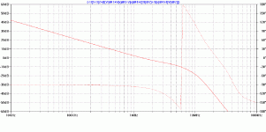
The inner Cherry loop is the most critical as it has 4 devices contributing roll-off in its forward path. InnerCherryLG.gif shows its Loop Gain. Note this is AT LEAST 2nd order at LF even with ‘pure Cherry’ providing an integrating loop. All of Cherry’s own designs have only 3 devices contributing roll-off (single BJT VAS, driver, output) so can usually manage a 1st order Loop Gain at LF with the integrating Cherry cap.
This means the best we can do is to kink the Nyquist curve from 180 (2nd order asymptote gain) as it nears Unity Gain or (-1,0). This is provided by C2 across the VAS emitter resistor at about 6MHz.
With the worst case reactive load (about 3n3), R1 10 in series with C2 provides a little more stability.
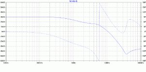
A stable inner Cherry loop becomes a nice integrator for the Main Loop Gain. MainCherryLG.gif Things don’t become wonky until the integrator (the Inner Cherry Loop) starts breaking down. So if the inner loop is good, the main loop is usually not problem.
When adjusting stability, R22 & C2 are the main points. R1 is selected for best behaviour on the nastiest capacitive loads.
Stability is also affected by the choice of gains. A bigger Cherry capacitor C1 actually increases Loop Gain around the Inner loop and makes it more unstable. But it also reduces loop gain for the Main Loop. Probably better to reduce Main Loop gain by decreasing Gm for the IPS. (bigger RDG)
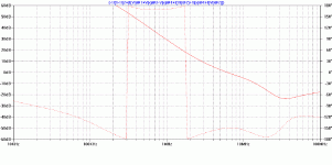
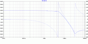
ClosedLoop8R.gif and ClosedLoop3n3.gif show the standard Closed Loop response and also the response with the most unstable load.
Attachments
Some of the small changes are as follows
Many of these don’t make any difference until the THD drops to a very low level.
I hope this has been interesting. I’ve tried very hard to suggest only stuff which I have at least vaguely tested.
I hesitate to ask Toni to try this for real. I’ve applied these techniques successfully to 50W amps with 1 output pair and a 100W 8R amp using 2 pairs. More devices would mean greater distance and inductance to the various devices. The possibility of disaster with his 400W monster frighten me and I’m not sure I would listen to a beach bum in Oz myself.
At the end of the day, these are all SPICE world results.
Conclusions
- R11/57 on the current mirror adjusted for equal Vce on Q1/2 and Q24/25
- C3 equal to the Cherry cap C1 added to the other side of the IPS current mirror. This has no effect on the present sim but has huge effect on +ve PSRR.
- Q6 collector taken to R56 instead of to GND or –V. I don’t know if KSA992 can be used with such a high Vce. The remaining THD is mainly 2nd and this reduces it slightly. It is likely the remainder is due to mismatched hfe on the drivers and output. I welcome suggestions for other causes.
- C11 1n across the bias spreader can be much smaller than its original 47u. This is a consequence of the Holy HiZ nature of this VAS. In traditional Miller, MIC, TPC or even TMC, voltage drive at the VAS collector mandates a stiff link to the lower driver. Here it’s chosen for stability reasons and has little effect on THD.
- The split for R22 is adjusted for nice overload behaviour.
Many of these don’t make any difference until the THD drops to a very low level.
I hope this has been interesting. I’ve tried very hard to suggest only stuff which I have at least vaguely tested.
I hesitate to ask Toni to try this for real. I’ve applied these techniques successfully to 50W amps with 1 output pair and a 100W 8R amp using 2 pairs. More devices would mean greater distance and inductance to the various devices. The possibility of disaster with his 400W monster frighten me and I’m not sure I would listen to a beach bum in Oz myself.
At the end of the day, these are all SPICE world results.
Conclusions
- ‘pure Cherry’ can be used to get very low distortion with simple circuits
- In particular, higher order harmonics and crossover spikes are greatly reduced
- Stability can be achieved with a VAS emitter resistor and judicious decoupling of this at VHF
- Both the inner Cherry loop and the Main Loop need to be carefully considered.
- ‘pure Cherry’ is useful even for large amps like Toni’s
This is an analysis of the files Toni (astx) posted in #109
http://www.diyaudio.com/forums/solid-state/235188-tpc-vs-tmc-vs-pure-cherry-15.html#post3489738
...
In general, you keep ‘clean’ GND pristine. But your C3/4 0u1 decouple the small signal stages to ‘clean’ GND. IMHO, this is truly evil and I’ve removed them. This will affect stability & THD in the sims slightly but I’ve not investigated this fully.
...
Dear kgrlee,
many thx for your support. You have done a really really good job on analyzing and optimizing my amp.
There's a lot of information which can be learned from!
Of course I am willing to test your "pure cherry" implementation the next days!
Best regards,
Toni
P.S.: The 0.1µ decoupling caps are necessary to keep HF away from input stage rails and/or avoid HF oscillations and must be connected to signal ground as the most of the pcb's other side is signal ground plane. Also don't forget I have very long ribbon cable to output stage. Don't know where I have this from. Old knowledge from designing HF circuits?
P.S.: The 0.1µ decoupling caps are necessary to keep HF away from input stage rails and/or avoid HF oscillations and must be connected to signal ground as the most of the pcb's other side is signal ground plane. Also don't forget I have very long ribbon cable to output stage. Don't know where I have this from. Old knowledge from designing HF circuits?[/FONT]
I feel that the ideal layout is a four-layer board where one layer is a dedicated "signal ground plane" layer and another is a dedicated "decoupling ground plane" layer. Audio signals and power should then be routed on a layer in-between these two planes.
This is close to what H.Ott suggests as the minimum requirement for a multi-layer board.I feel that the ideal layout is a four-layer board where one layer is a dedicated "signal ground plane" layer and another is a dedicated "decoupling ground plane" layer. Audio signals and power should then be routed on a layer in-between these two planes.
He states 6layer as the fewest that gets near optimum.
I feel that the ideal layout is a four-layer board where one layer is a dedicated "signal ground plane" layer and another is a dedicated "decoupling ground plane" layer. Audio signals and power should then be routed on a layer in-between these two planes.
You are right. Here we have the "cheap" version with 2 layers...
BR, Toni
This is close to what H.Ott suggests as the minimum requirement for a multi-layer board.
He states 6layer as the fewest that gets near optimum.
Maybe the "ultra supa dupa low noise" edition of this amp get's these 6 layers ...
BR, Toni
... Of course I am willing to test your "pure cherry" implementation the next days!
Sorry - I took the wrong smiley - I meant this one:
BR, Toni
Toni says he found the TMC version unstable. If our SPICE model is to be trusted, it should at least suggest problems in this area. Accurate simulation is difficult as this is a big amp with 8 pairs of outputs. Stray capacitances and lead inductances will have much more influence than with a simple 50W amp with only 1 pair of outputs close to the VAS and other stuff. Remember 20nH / inch!
I won’t bore you with a full stability analysis. I couldn’t get the model to oscillate on any ‘linear’ measure or even .TRANS though it came close with certain capacitive loads. The Closed Loop response CL3n3.gif shows what happens with just 3n3 on the output. The sharp Q of the peak is certainly suggests it won’t take much to push this amp into oscillation.
TMC.gif Do we believe this model? Probably. Real life is probably more twitchy cos loadsa extra strays & parasitics.
Where did you get the cap and resistor values from ??
Do you know how to establish the correct values ??
No wonder it shows instability.
Dear Manso,
thank you for response. The base stoppers of drivers are 10R after 68R - so in sum 78R. To base of other bjt in sum 20R. Do you think there could be a problem? Maybe a oscillation loop between the two drivers? If so, I will change them to 47R - sim shows no problems on doing so.
Cascode base stoppers: afaik Bob and Douglas haven't used them in their books? Is there more information about this or experience?
BR, Toni
As long as the base resistors are all of same value there shouldnt be anyproblems.
None of them have mentioned it because maybe they are unaware or havent experienced problems with it, or wideband and RF amplification is not their speciality. Nowadays however with the increasing bandwith that can be achieved it is important to cover all bases. In a design like this one its not that important as it has meagre bandwith.
I have thought about using base stopper resistors also for cascode bjt's after reading a document about EF oscillation somewhere on this server...
Unstable TMC?
I couldn't get it to oscillate with Toni's original values using the methods in my post #177. There was little change to THD or the 20kHz residual on what I simmed (which didn't oscillate)
Please excuse me if I didn't spend zillion hrs working on something which doesn't have any potential (or real) advantage over 'pure Cherry' ... and I believe to be evil.
And Yes. I know Toni has some later TMC versions which were stable. But its a lot of work doing full stability .. even in SPICE world. You might like to try both his new & old versions. If you can modify the models to show 'old unstable' and 'new stable', you will have improved the sum of human knowledge and deserve our adoration.
I'll post my own final model and the tools for my results in a bit.
Toni says he found the TMC version unstable. If our SPICE model is to be trusted, it should at least suggest problems in this area. Accurate simulation is difficult as this is a big amp with 8 pairs of outputs. Stray capacitances and lead inductances will have much more influence than with a simple 50W amp with only 1 pair of outputs close to the VAS and other stuff. Remember 20nH / inch!
I won’t bore you with a full stability analysis. I couldn’t get the model to oscillate on any ‘linear’ measure or even .TRANS though it came close with certain capacitive loads. The Closed Loop response CL3n3.gif shows what happens with just 3n3 on the output. The sharp Q of the peak is certainly suggests it won’t take much to push this amp into oscillation.
TMC.gif Do we believe this model? Probably. Real life is probably more twitchy cos loadsa extra strays & parasitics.
I used Michael Kiwanuka's method of just moving R27 in Toni's original from earth to the output in a working and stable TPC version. Yes. I know there are better methods to get evil TMC stable. You may like to download Toni's model from post #109 which is what I used .. & play yourself.Where did you get the cap and resistor values from ??
Do you know how to establish the correct values ??
No wonder it shows instability.
I couldn't get it to oscillate with Toni's original values using the methods in my post #177. There was little change to THD or the 20kHz residual on what I simmed (which didn't oscillate)
Please excuse me if I didn't spend zillion hrs working on something which doesn't have any potential (or real) advantage over 'pure Cherry' ... and I believe to be evil.
And Yes. I know Toni has some later TMC versions which were stable. But its a lot of work doing full stability .. even in SPICE world. You might like to try both his new & old versions. If you can modify the models to show 'old unstable' and 'new stable', you will have improved the sum of human knowledge and deserve our adoration.
I'll post my own final model and the tools for my results in a bit.
One of the things that allows this amp to be so stable with such little internal compensation is the relatively high parasitic C at the OPS input. This can be visualized as a large cap to ground after the total base stopper resistance. However this capacitance is a proverbial lightning rod for high order switching harmonics of the OPS.
On the note of consistency in stability, I think it's a good idea to use .12R emitter resistors in the OPS so they can be biased higher; otherwise they may be too slow in the crossover region and too fast outside of it, and you will oversize your compensation in order to compensate for the slow region. Unfortunately that makes an amp like this dissipate a lot of heat. A more unflattering option is to slow down the outputs at high current to match speed in the crossover region. I think this can be done by bridging the base and emitter resistor with a cap, say 3-5 times the Cbe of the transistor in question.
For C5200/A1943, Cbe is quite large. In addition to this, .47R emitter resistors mean they need to be biased low to get the null point (13mV per Re) - so OPS speed is probably bouncing up and down wildly while in operation. Moving to faster outputs would probably allow for more consistent stability and therefore lower compensation.
kgrlee, I make my own C5200/A1943 SPICE models which are included in the standard.txt file I posted way back. I matched Ft to the datasheet - why don't you use those models?
Like any well designed, linear amplifier, the max slew rate, step response and group delay are entirely consistent with the small signal frequency responses in post #182. ie it doesn't exhibit TID & other esoteric distortions.kgrlee, how is the slewing, step response and group delay behavior? You can view group delay by clicking the phase axis in AC analysis.
IMHO, stupid slew rates only come into play when the amp is overloaded by VERY stupid high level HF. Then the most important factor is not slew rate but how
- the amp behaves on overload
- how quickly it recovers
Also good was the use of bigger R11/57 on the IPS current mirror. These two measures give good overload behaviour without extra clamp bits in this simple circuit.
Keantoken, thank you for your models which I've downloaded already.I make my own C5200/A1943 SPICE models which are included in the standard.txt file I posted way back. I matched Ft to the datasheet - why don't you use those models?
But my evil plan is really to persuade more people to try 'pure Cherry' ... and give them some tools to solve the problems other gurus have found. For this, 'real life' examples are my target.
eg 'pure Cherry' is unsuitable for eg 'evil Triples + supa VAS'. It's really about getting supa performance from much simpler circuits. Toni's amp is already a good example of this type of thinking. I'm hoping to take it one stage further and get some 'real life' evidence to go with my 20+ yr old Jurassic memories.
I know Toni has already tried C5200/A1943 but he has published more 'real life' results with the original devices.
There is a 3rd option. That is to do NOTHING to slow down the VAS as it drives the devices across the xover region. That means no plain Miller, TPC or even TMC. Because these all take some HF feedback from the VAS collector, they slow that point down.A more unflattering option is to slow down the outputs at high current to match speed in the crossover region.
The ultimate result of this thinking is 'pure Cherry'. That's why it shows very little xover and is very insensitive to exact Iq. The other methods all attempt to make the VAS output LoZ ... but in doing so, they invariably slow it down.
'pure Cherry', with HiZ at that point, converts the spiky High Order Gm xover distortions .. into smooth low order hfe matching ones. AND it increases Loop Gain hugely too which makes the low order hfe matching distortions of little significance.
Last edited:
I fully agree on slew rate. It is important that slewing doesn't cause stored energy (IE instant recovery) in the circuit in the case someone parks next to your house with the CB radio full blast.
You can get an EF3 stable with your compensation scheme if you use a shunt network at the VAS output to emulate the EF2 driver parasitics, without reintroducing the associated distortions. Using an EF2 also allows you to have less shunt capacitance here, meaning less high order switching harmonics.
You can get an EF3 stable with your compensation scheme if you use a shunt network at the VAS output to emulate the EF2 driver parasitics, without reintroducing the associated distortions. Using an EF2 also allows you to have less shunt capacitance here, meaning less high order switching harmonics.
- Home
- Amplifiers
- Solid State
- 2stageEF high performance class AB power amp / 200W8R / 400W4R
