Many many thanks for your insight Scott.
Sorry if these are daft questionsjust trying to expand my knowledge now.
You say "the gate voltage equilibrates with the back to back diodes biased by the gate leakage current. Diodes ? plural, two of. Do you mean the intrinsic "diodes" found in a normal junction FET and if so, that the leakage is both sufficient and presumably equally matched between the two ? Sufficient on their own to be used for biasing. (I am thinking that as the FET is symetrical there must be two diodes.)
Is there any reason why just one diode is shown in the picture and also in the device in Jaccos link.
I appreciate the electret in isolation has no DC path of its own... I have just never heard of FET's being left essentially with the gate OC to self bias if that understanding is correct.
So legarem is going to need a fairly specific FET for this to work.
Yes, the other diode is the gate junction. To be sure you can just use back to back low leakage diodes. At zero volts a diode has a resistance of around 2VT/Is where Is is the saturation current and VT is 25.9mV (kT/q). This can be 10^15 Ohms in some cases. Say you have a pico amp of leakage, the diode looks like .058/10^-12 Ohms or so. Computer diodes have high Is and don't work well.
Sorry, it's not here but another site where every few months this comes up and sorry also I don't have an easy to read reference that explains this.
Last edited:
This is what I strongly suspect
I have it working on my bench right now with a 2SK170 and 2-2N4418 with the drains cut off used as back to back diodes. The 2SK170's used as diodes contribute too much capacitance. Do you know how much C the electret cartridge has? We shoud be able to get you up and running with something. 2SK222's are hard to find but they would be good but as followers BF862's work also and you could use extras as the diodes.
I have it working on my bench right now with a 2SK170 and 2-2N4418 with the drains cut off used as back to back diodes. The 2SK170's used as diodes contribute too much capacitance. Do you know how much C the electret cartridge has? We shoud be able to get you up and running with something. 2SK222's are hard to find but they would be good but as followers BF862's work also and you could use extras as the diodes.
I don't have any idea of the electret input capacitance of the cartridge. I really have to find a fet alone because there's not too much place in the cartridge.
pinout
It's SGD, viewed from fet azz, trust me. (cross my heart and hope to die)
Yes, the other diode is the gate junction.......................
Many thanks again Scott for the explanation. Learnt something new today.
I don't have any idea of the electret input capacitance of the cartridge. I really have to find a fet alone because there's not too much place in the cartridge.
In that case it can't hurt to just try either a 2SK30 or 2SK118 which should be easily available and just tack them in and see (gate floating which usually works). They will run at Idss so the 30k might be too big, you could try it on the bench first.
It's SGD, viewed from fet azz, trust me. (cross my heart and hope to die)
Hi Jacco
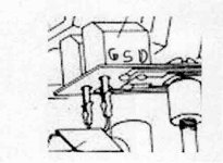
I zoomed your cartridge internal picture to see how the wires were connected.
I can clearly see that the fet are connected as source followers.
The pinout is GSD. Left pins of the fet goes to the electret needle
Attachments
That would the first, even the oldest Toshiba JFETs in a metal can (e.g. SK11/2SK12) have the Gate inbetween the Drain and Source.
Other Japanese N-channels, K68, K150, K163, even uPA68h : DGS or SGD.
GSD is a common lead sequence for Japanese MOSFETs, e.g. K213-K216, K2013.
(an artist impression doesn't make it right)
Toshiba Gate diode for Mooly =>
=>
Other Japanese N-channels, K68, K150, K163, even uPA68h : DGS or SGD.
GSD is a common lead sequence for Japanese MOSFETs, e.g. K213-K216, K2013.
(an artist impression doesn't make it right)
Toshiba Gate diode for Mooly
=>Attachments
(an artist impression doesn't make it right)
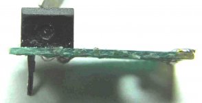
Here is the real beast
Attachments
As I received my K118 today I looked at the CP-Y internals
I think I have a big problem, If I try to look at the resistance of the Needle (electret) R and L to the needle casing, One side (signal) R or L of the electret to the needle casing don't show any resistance. The other side is showing 6 ohms
I think I reached the end of my dream
What is the resistance of an electret between signal and ground ?
As I don't remember which channel played, I can't identify if the one showing a resistance of 6 ohm is the good or the bad one.
This is sad to reach this end after all the work done.
Thanks a lot for your help
Finally, I found a source of CP-Y stylus so my horse is not dead.
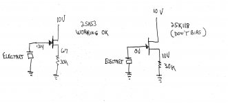
Before receiving me new stylus, I want to make the cartridge alive again so I made tests to find a 2SK53 fet replacement for the bad one.
Here is what I got with values reading with the 2SK53 FET
I tried the 2SK118 and it didn't work at all. It didn't bias.
1- Do I have to choose another FET than the K118 ? If yes, what could I use?
2- Changing the source resistor with a lower one ?
3- Biasing the K118 with a resistor from S to G ?
4- Make the K118 in amplification mode instead of source follower ?
Any recommendation is welcome
Thanks a lot
Attachments
Well Scott has considerably more knowledge on this subject than myself so hopefully he might be able to add something.
I'm not sure how suitable these might be,
2SK1109
http://www.datasheetcatalog.org/datasheets2/46/46317_1.pdf
I'm not sure how suitable these might be,
2SK1109
http://www.datasheetcatalog.org/datasheets2/46/46317_1.pdf
Finally, I found a source of CP-Y stylus so my horse is not dead.
Before receiving me new stylus, I want to make the cartridge alive again so I made tests to find a 2SK53 fet replacement for the bad one.
Here is what I got with values reading with the 2SK53 FET
I tried the 2SK118 and it didn't work at all. It didn't bias.
1- Do I have to choose another FET than the K118 ? If yes, what could I use?
2- Changing the source resistor with a lower one ?
3- Biasing the K118 with a resistor from S to G ?
4- Make the K118 in amplification mode instead of source follower ?
Any recommendation is welcome
Thanks a lot
I have some trepepidation about making suggestions without being able to physically see what's up. I have problems with the numbers on that picture, where does the voltage come from on the gate and since this is an ultrahigh impedance circuit how is it measured. The source to gate voltage in both cases is more than enough to pinch off either FET yet the 2SK118 is a short (?).
I think your meter is causing false readings. First try a 2.2k on the 2SK118 rather than 30K, I still can't find any info on the 2SK53 and it might have been an ultra low Idss FET (6.7V/30k =~ 225uA). This would be way down on the tail of the 2SK118's distribution. The source follower should bias up at ~Idss in this configuration. If this works you would need to replace both sides.
Last edited:
If this works you would need to replace both sides.
For matching, the mismatch would be enough possibly to compromise the channel balance. The R, O, or Y grade 2SK118's should all work, some of the GR grade would still have too much Idss for 2.2K. The R grade was used in electret microphones for long battery life.
Last edited:
I made my measurements with my fluke multimeter.
I'll try 2.2K at the source instead of the 30K
In many K118 circuits, I see a 1G resistor from S to G to bias the K118
I suppose I need some.
Thanks again
It should work without the 1G resistor, the 2SK53 does. You will have to buy chip versions to fit them in. The cheap Chinese mics use 0805's where someone soldered little leads on them and dipped them in epoxy. I have no source for the tiny 1/8W ones that you get when opening vintage Nakamichi mics. Most leaded ones available are huge.
- Status
- This old topic is closed. If you want to reopen this topic, contact a moderator using the "Report Post" button.
- Home
- Design & Build
- Parts
- 2SK53 FET